Bidirectional thrust bearing
A two-way thrust bearing and thrust pad technology, applied in bearing components, shafts and bearings, bearing cooling, etc., can solve problems such as short service life, poor lubrication, and increased oil temperature
- Summary
- Abstract
- Description
- Claims
- Application Information
AI Technical Summary
Problems solved by technology
Method used
Image

Examples
Embodiment 1
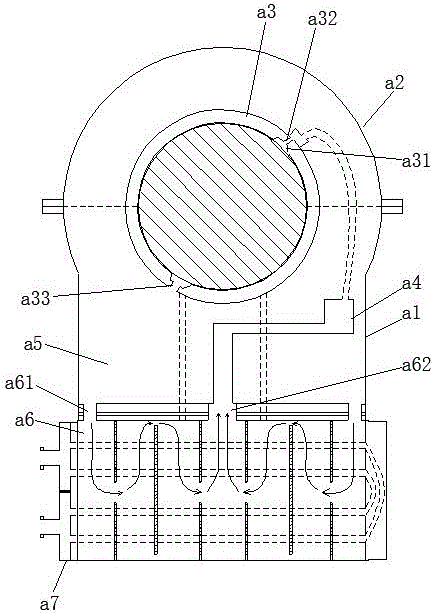
[0120] A two-way thrust bearing, such as Figure 5 , Image 6 and Figure 7 As shown, it includes bearing seat 1, bearing cover 2, shoe seat 3, support shoe 41, first thrust shoe 42, second thrust shoe 43, first thrust disk 51, second thrust disk 52, first oil chamber 6, The second oil chamber 7, cooler 8 and oil cover 9, the bearing cover 2 is used to cover the top of the bearing seat 1, the shoe seat 3 is fixed on the bearing seat 1, and the supporting shoe 41 is fixed on the shoe The inner diameter side of the seat 3, the two axial ends of the shoe seat 3 are the front end and the rear end respectively, the first thrust shoe 42 is fixed on the front end of the shoe seat 3, and the second thrust shoe 43 is fixed on the shoe seat 3 The rear end of the first thrust disc 51 is attached to the front end of the first thrust pad 42, the second thrust pad 43 is attached to the rear end of the second thrust pad 43, and the first thrust disc 51 and the second thrust disc 52 are coa...
Embodiment 2
[0133] The difference from Embodiment 1 is that: Figure 19 As shown, the inner surface of the support shoe 41 includes at least two oil injection grooves 411 , and the oil injection grooves 411 are spirally distributed on the inner surface of the support shoe 41 . With the conventional oil tank structure, the oil film fracture is prone to occur in the area far away from the oil tank. The sliding friction of the oil film fracture zone produces large heat, the heat conduction speed is slow, and it is easy to cause the burning of the pads; this method can effectively prevent the fracture of the oil film between the bearing pad and the shaft body.
Embodiment 3
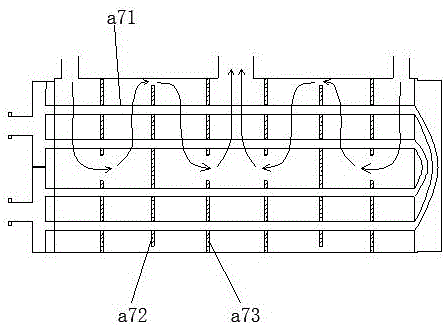
[0135] The difference from Embodiment 1 is that: Figure 20 As shown, the oil discharge groove 412 includes a first oil discharge groove 412a and a second oil discharge groove 412b, the first oil discharge groove 412a and the second oil discharge groove 412b are respectively located at the two ends of the oil injection groove 411, and the first oil discharge groove 412a is connected to the oil injection groove 412b. The distance between the oil grooves 411 is 30mm, the distance between the second oil discharge groove 412b and the oil injection groove 411 is 30mm, the first oil discharge groove 412a is provided with an oil discharge hole 414, and the first oil discharge groove 412a passes through the oil discharge hole 414 and The first oil chamber 6 communicates, and the second oil discharge groove 412 b is a semi-open groove, directly communicating with the first oil chamber 6 .
PUM
 Abstract
Description
Claims
Application Information
 - R&D
- Intellectual Property
- Life Sciences
- Materials
- Tech Scout
- Unparalleled Data Quality
- Higher Quality Content
- 60% Fewer Hallucinations
Browse by: Latest US Patents, China's latest patents, Technical Efficacy Thesaurus, Application Domain, Technology Topic, Popular Technical Reports.
© 2025 PatSnap. All rights reserved.Legal|Privacy policy|Modern Slavery Act Transparency Statement|Sitemap|About US| Contact US: help@patsnap.com