Textile wastewater treatment system<0}

A technology of textile wastewater and treatment system, which is applied in the direction of textile industrial wastewater treatment, multi-stage water treatment, water/sewage treatment, etc., which can solve the problem of difficult discharge or reuse of wastewater, complex and cumbersome process flow, and unfavorable biological bacteria. The problem of seed growth and other problems can be solved, and the effect of good decolorization effect, stable system operation and high degree of automation can be achieved.

Inactive Publication Date: 2017-05-24
JIANGSU YONGYI ENVIRONMENTAL PROTECTION TECH CO LTD
View PDF4 Cites 4 Cited by
  • Summary
  • Abstract
  • Description
  • Claims
  • Application Information

AI Technical Summary

Problems solved by technology

Bleaching and dyeing wastewater contains additives such as dyes, sizing agents, and surfactants. This type of wastewater has a large amount of water and low concentration and chromaticity. If only physical and chemical treatment is used, the effluent is also between 100 and 200mg / l, and the chromaticity It can also meet the emission requirements, but the amount of pollution is greatly increased, the cost of sludge treatment is higher, and it is easy to cause secondary pollution
[0005] Other commonly used treatment methods usually have complex and cumbersome process flow, high operating costs and unsatisfactory effects in actual wastewater treatment operations
The main reason is that the wastewater quality is unstable, the chroma is high, or the additives used in some processes are not conducive to the growth of biological strains, so it is difficult to achieve standard discharge or reuse of wastewater

Method used


Image

  • Textile wastewater treatment system&lt;0}
  • Textile wastewater treatment system&lt;0}

Examples


Embodiment

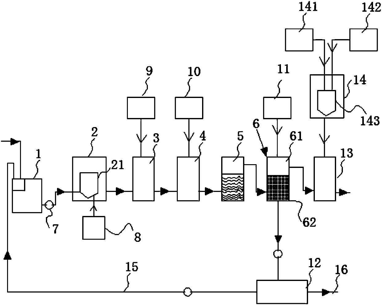
[0033] Embodiment: a kind of textile wastewater treatment system, such as figure 1 As shown, it includes a grid grease trap 1 that can collect textile wastewater, and a decolorization pretreatment tank 2, a conditioning tank 3, a hydrolysis acidification tank 4, a contact oxidation Pool 5 and reaction sedimentation tank 6;

[0034] A water pump 7 is provided on the wastewater pipeline 15 between the grid grease trap 1 and the decolorization pretreatment pool 2, and a central reaction barrel 21 is arranged in the decolorization pretreatment pool 2, and the decolorization pretreatment pool 2 The periphery is provided with a decolorizing agent feeding device 8, and both the decolorizing agent and waste water enter from the bottom of the central reaction tank;

[0035] The periphery of the regulating pool 3 is provided with an acid-base feeding device 9, and the acid-base feeding device 9 communicates with the regulating pool 3, and the periphery of the hydrolytic acidification p...


PUM


Abstract

The invention discloses a textile wastewater treatment system. The textile wastewater treatment system comprises a grid oil separator capable of collecting textile wastewater, as well as a decolorizing pretreatment pool, a regulating reservoir, a hydrolysis acidification pool, a contact oxidation pool and a reactive precipitation pool which are sequentially communicated with the grid oil separator through wastewater pipelines, wherein <0}the reactive precipitation pool comprises a top reaction zone and a bottom settling zone; the bottom settling zone is connected with a press filter through a sludge pipeline; the press filter is connected with the grid oil separator through a wastewater pipeline; the press filter discharges sludge through the sludge pipeline; the top reaction zone is connected with a disinfection pool through a wastewater pipeline; the periphery of the disinfection pool is provided with a chlorine dioxide generator; the textile wastewater treatment system further comprises a control system. <0}By virtue of reasonable combination of biochemistry and physical chemistry, a textile wastewater treatment system which is low in cost, high in treatment efficiency and stable in system operation is formed; furthermore, by virtue of a PLC (Programmable Logical Controller), a PH sensor, a flowmeter and the like, the system is automatic in dosage control, high in control process automation degree and accurate in control, and is capable of lowering the labor cost.

Description

technical field [0001] The invention belongs to the technical field of wastewater treatment and relates to a textile wastewater treatment system with a control system. Background technique [0002] The textile printing and dyeing industry is a large discharge of industrial wastewater. The wastewater mainly contains dirt, oil, salt on textile fibers, and various sizing, dyes, surfactants, auxiliaries, acids and bases added during processing. [0003] Wastewater is characterized by high concentration of organic matter, complex composition, deep and changeable color, large pH changes, and large changes in water quantity and quality. It is a difficult-to-treat industrial wastewater. With the development of chemical fiber fabrics, the rise of imitation silk and the improvement of overall requirements after printing and dyeing, a large number of refractory organic substances such as PVA (polyvinyl alcohol) slurry, rayon hydrolyzate, new dyes, and auxiliaries have entered textile p...

Claims


Application Information

Patent Timeline
Patent Type & Authority Applications(China)
IPC IPC(8): C02F9/14C02F103/30
CPCC02F9/00C02F3/28C02F2103/30C02F2301/08C02F2303/04C02F1/001C02F1/40C02F3/02C02F1/50C02F1/5236C02F1/5281C02F1/56C02F1/66
Inventor 刁永辉
Owner JIANGSU YONGYI ENVIRONMENTAL PROTECTION TECH CO LTD
Why Eureka
Try Eureka