Polysilicon waste gas treatment and waste heat utilization device and process

A waste gas treatment and polysilicon technology, applied in the direction of halosilane, silicon compound, heat exchanger type, etc., can solve the problems of polysilicon output and product quality, consumption of large lye, waste of chlorosilane materials, etc., to prevent fire and Explosion accidents, consumption reduction, and stability assurance effects

Pending Publication Date: 2017-05-31
LESHAN VOCATIONAL & TECHN COLLEGE +2
View PDF6 Cites 3 Cited by
  • Summary
  • Abstract
  • Description
  • Claims
  • Application Information

AI Technical Summary

Problems solved by technology

[0004] 1. The process is too simple, which is easy to cause waste of resources
[0005] The polysilicon production process is mainly composed of rectification process, reduction process, CDI process, hydrogenation process, etc. The waste gas from these processes contains a certain amount of chlorosilane (mainly SiHCl 3 、SiCl 4 and SiH 2 Cl 2 ), if it directly enters the waste gas treatment process, it will not only cause waste of chlorosilane materials, but also consume a large amount of lye, and at the same time, the treatment cost of solid waste residue will also greatly increase
[0006] 2. Poor applicability
[0007] The polysilicon production process is a continuous and complete closed-loop process. If there is a problem in a certain process or link in the production process, it may affect the stability of the polysilicon production system, resulting in a sharp increase in the amount of waste gas. For example: ①Due to the fluctuation of natural gas pressure, the pressure of water vapor may rise instantaneously, resulting in the phenomenon of "running material" due to the increase of temperature and pressure at the top of the distillation column in the rectification process; ②CDI process caused by various reasons Overload operation will cause a sharp increase in the amount of exhaust gas; ③equipment failure, maintenance, etc. will also generate a large amount of exhaust gas
[0008] 3. Serious environmental pollution
[0009] It is easy to generate a large amount of white smoke due to insufficient waste gas treatment, which not only causes waste of resources, but also causes serious pollution to the environment
[0010] 4. Poor security
[0013] 5. The stability and product quality of the polysilicon production system are affected
[0014] Due to the frequent occurrence of fire and explosion accidents, the stability of the polysilicon production system is seriously affected, and it is often necessary to reduce and adjust each process. Therefore, polysilicon output and product quality are greatly affected
[0015] 6. Large heat loss
[0016] Polysilicon waste gas mainly contains SiHCl 3 、SiCl 4 、SiH 2 Cl 2 、H 2 , N 2 , HCl, etc., in the tail gas treatment process, SiHCl 3 、SiCl 4 、SiH 2 Cl 2 , HCl, etc. will chemically react with the lye, which will generate a lot of heat. Part of this part of the heat will be lost with the liquid-solid reactants into the lye pool, and the other part will be brought into the liquid-sealed water tank and air loss with the gas, which is not only easy Cause the vented gas to catch fire or explode, and also cause a lot of heat waste

Method used


Image

  • Polysilicon waste gas treatment and waste heat utilization device and process
  • Polysilicon waste gas treatment and waste heat utilization device and process
  • Polysilicon waste gas treatment and waste heat utilization device and process

Examples


Embodiment Construction

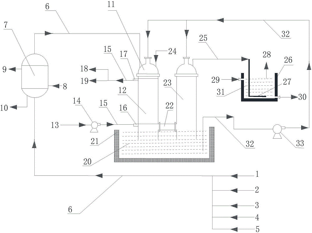
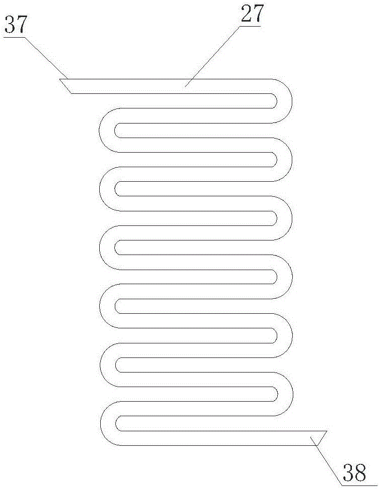
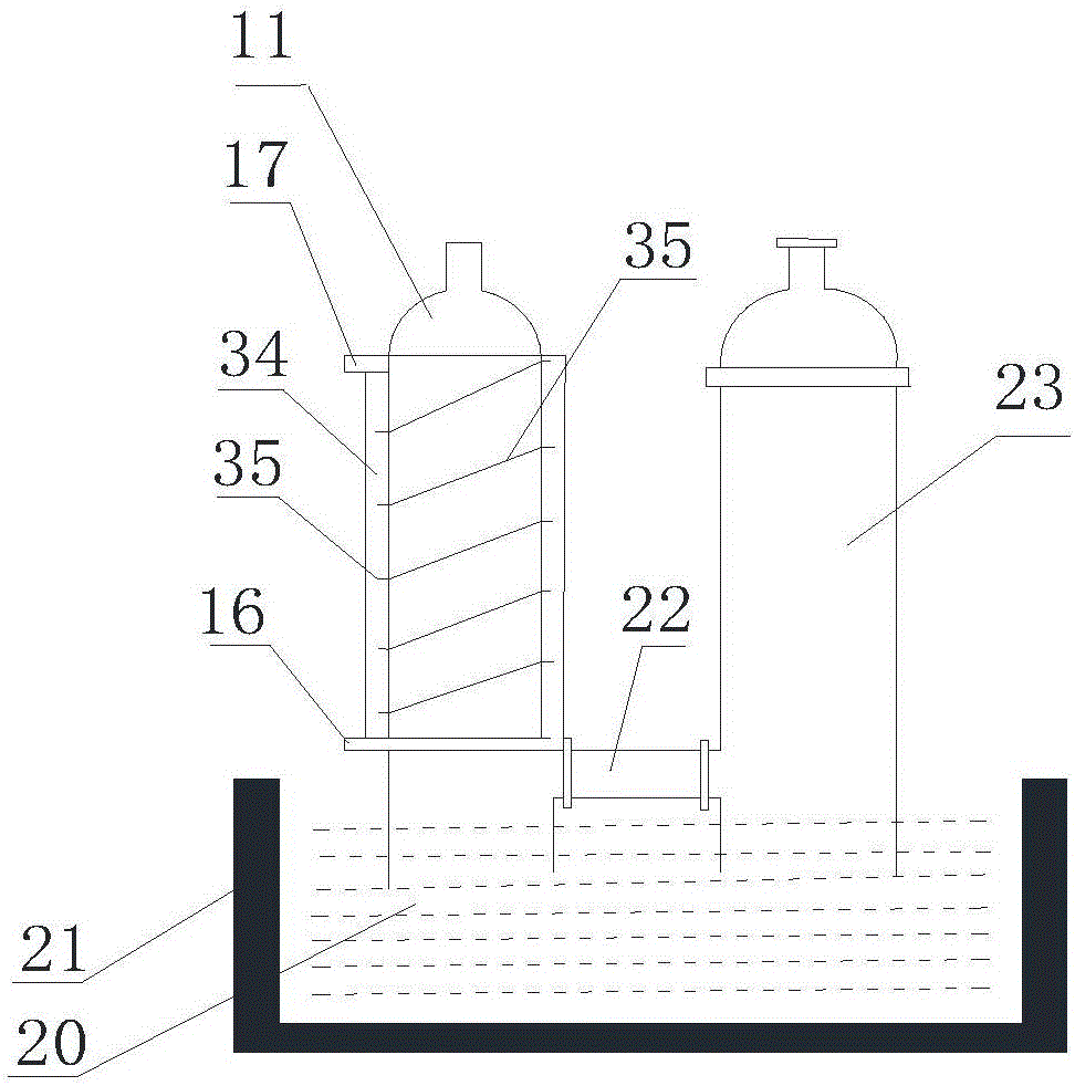
[0038] Reference Figure 1-4 , A polysilicon waste gas treatment and waste heat utilization device, including waste gas condensation recovery tank 7, waste gas leaching tower A11, waste gas leaching tower B23, lye tank 21 and liquid sealed water tank 26, said waste gas condensation recovery tank 7 is connected in series In the exhaust gas pipe 6 used for exhaust gas collection, the end of the exhaust pipe 6 is connected to the exhaust gas washing tower A11, the bottom of the exhaust gas washing tower A11 is set in the lye tank 21, and the exhaust gas washing tower A11 is connected by a connecting pipe 22 The exhaust gas leaching tower B23, the bottom of the exhaust gas leaching tower B23 is arranged in the lye pool 21, the exhaust gas leaching tower B23 is connected to the vent pipe 27 arranged in the liquid-sealed water tank 26 through the exhaust pipe 25; the lye pool 21 is also connected to the bottom of the waste gas leaching tower A11 and the waste gas leaching tower B23 t...


PUM

PropertyMeasurementUnit
autoignition temperatureaaaaaaaaaa

Abstract

The invention discloses a polysilicon waste gas treatment and waste heat utilization device and a polysilicon waste gas treatment and waste heat utilization process. The waste gas treatment and waste heat utilization device comprises a waste gas condensation recovery tank, a waste gas elution column Alpha, a waste gas elution column B, an alkaline liquor pond and a liquid seal water tank, wherein the waste gas condensation recovery tank is connected in series to a waste gas pipe used for gathering the waste gas, the tail end of the waste gas pipe is connected with the waste gas elution column Alpha, the bottom part of the waste gas elution column Alpha is arranged in the alkaline liquor pond, the waste gas elution column Alpha is connected with the waste gas elution column B through a communication pipe, the bottom part of the waste gas elution column B is arranged in the alkaline liquor pond, the waste gas elution column B is connected with a blow-down pipe arranged in the liquid seal water tank through an exhaust pipe, the alkaline liquor pond is further connected with the bottom parts of the waste gas elution column Alpha and the waste gas elution column B through an alkaline liquor pipe, an alkaline liquor pump is arranged in a pipeline of the alkaline liquor pipe, and a waste heat utilization mechanism is arranged in a reaction area of the waste gas elution column Alpha. Due to the polysilicon waste gas treatment and waste heat utilization device and the polysilicon waste gas treatment and waste heat utilization process, the chlorosilane is effectively recycled, environmental pollution is solved, and energy consumption is reduced.

Description

Technical field [0001] The invention belongs to the technical field of polysilicon production and manufacturing, and specifically relates to a polysilicon waste gas treatment and waste heat utilization device and process. Background technique [0002] With the rapid development of the solar photovoltaic industry, the demand for polysilicon will continue to grow. Most of the waste gas produced in the production of polysilicon are flammable, explosive, toxic and hazardous substances, mainly from the distillation process, the reduction process, the exhaust gas recovery process (CDI), the hydrogenation process and the synthesis process. [0003] At present, polysilicon production enterprises basically use alkaline solution leaching method to treat polysilicon waste gas, which has the advantages of simple process, low investment and operating cost. However, with the rapid expansion of the production capacity and scale of polysilicon plants in recent years, the amount of waste gas gener...

Claims


Application Information

Patent Timeline
Patent Type & Authority Applications(China)
IPC IPC(8): B01D53/78B01D53/00C01B33/107F28B1/02F28C3/08
CPCB01D53/002B01D53/78F28B1/02F28C3/08C01B33/1071Y02P20/129
Inventor 胡小东姜希猛崔明现贾曦张东
Owner LESHAN VOCATIONAL & TECHN COLLEGE
Why Eureka
Try Eureka