Pulverized coal fired boiler hearth provided with variable-section combustor area and adapting to flexible peak shaving

A pulverized coal boiler and burner technology, applied in the combustion chamber, combustion method, combustion equipment, etc., can solve the problems of low temperature level and ambient temperature, fuel oil or natural gas consumption, low heat transfer intensity of water wall, etc., and achieve low load Improved combustion stability, reduced burner elevation, and flexible peak shaving

Active Publication Date: 2017-05-31
DONGFANG BOILER GROUP OF DONGFANG ELECTRIC CORP
View PDF18 Cites 1 Cited by
  • Summary
  • Abstract
  • Description
  • Claims
  • Application Information

AI Technical Summary

Problems solved by technology

[0007] 1) The existing boiler scheme design needs to consider the full-load coal type adaptability and anti-slagging ability, so the thermal index of the boiler furnace is relatively low. Therefore, when a single mill / single-layer burner is put into operation, the entire furnace The temperature level and ambient temperature are low, so it is difficult to achieve stable combustion of a single mill, and usually two mills need to cooperate with each other to achieve a stable combustion capacity of 30% BMCR;
[0008] 2) Due to the low combustion intensity in the lower burner area of ​​the prior art, and the furnace temperature is not high enough, the burnout rate of the pulverized coal fed into the lower burner is low, reducing the boiler efficiency;
[0009] 3) When the boiler is ignited and the load is increased, the coal pulverizer is put into operation one by one. Generally, the coal pulverizer corresponding to the lower burner is put into operation first. If the temperature of the furnace is not high enough, the pulverized coal will not ignite when it enters the furnace. Therefore, before putting in the pulverized coal It is often necessary to put in auxiliary fuel oil or natural gas first to raise the temperature in the furnace to the condition where coal is allowed to be fed. Because the furnace temperature rises slowly in the prior art, this will cause a large amount of fuel oil or natural gas consumption, making the cost of each start-up high. no less
[0010] 4) Since the inclination angle of the cold ash hopper has certain requirements, generally not less than 55 degrees, the height of the cold ash hopper in the prior art is very large
These two factors have resulted in a large boiler height and high boiler manufacturing costs
[0011] 5) The flue gas temperature in the lower half of the cold ash hopper is low, resulting in low heat transfer intensity of the water wall in this area and insufficient utilization of the heating surface
[0012] 6) The existing furnace type has a large cross-sectional area, the flue gas temperature in the lower burner area is low, and the heating speed of the pulverized coal airflow is slower, which is not conducive to the rapid precipitation of volatile components, and the NOx control is not ideal
The flue gas temperature in the lower burner area of ​​the existing furnace structure is low, the reduction reaction speed is inhibited, and the NOx in this area cannot be fully reduced

Method used


Image

  • Pulverized coal fired boiler hearth provided with variable-section combustor area and adapting to flexible peak shaving
  • Pulverized coal fired boiler hearth provided with variable-section combustor area and adapting to flexible peak shaving
  • Pulverized coal fired boiler hearth provided with variable-section combustor area and adapting to flexible peak shaving

Examples


Embodiment 1

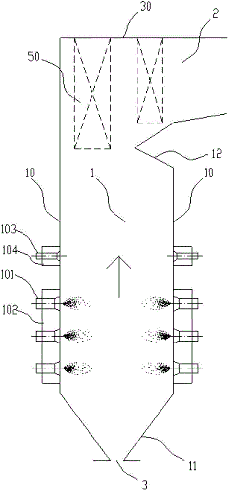
[0040] refer to image 3 As shown in Fig. 1, a pulverized-coal boiler furnace with variable burner area adapting to flexible peak regulation, the furnace cross-sectional area of ​​different burner layers is not exactly the same, and the furnace cross-sectional area of ​​the burner area gradually expands along the flue gas flow direction (ie A2 image 3 As shown in the hearth of the П-type pulverized coal furnace, a first-level slope section is set in the burner area of ​​the furnace. The slope section is directly connected to the cold ash hopper, and the front and rear walls of the slope section are arranged symmetrically. The inclination angle between the slope section and the flue gas flow direction (vertical upward direction in the figure) is in the range of 5° to 35°. The burners include 2 layers of burners arranged in the variable section furnace, and 1 layer of upper layer burners (downstream burners) above. A layer of overfired air is arranged downstream of the flue gas ...

Embodiment 2

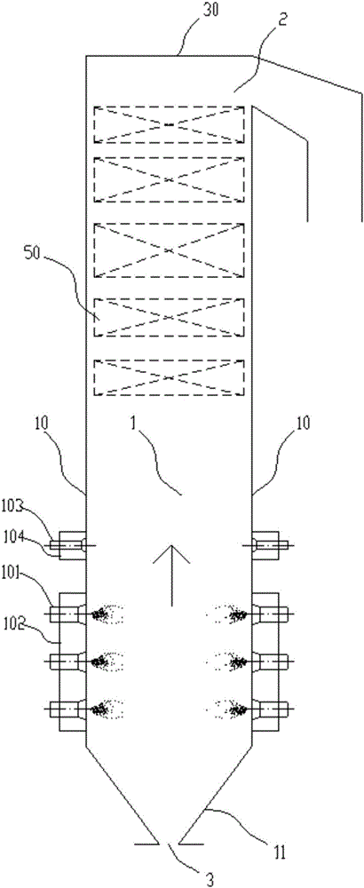
[0042] refer to Figure 4 As shown, this embodiment is basically the same as Embodiment 1, and the difference is that two grades of slope sections are set in the burner area of ​​the furnace to form a furnace with a variable cross-sectional area, the vertical section transition between the slope section and the cold ash hopper, and the slope section between each slope section The two-layer burner of the variable-section furnace is installed on the water-cooled wall of the vertical section, and there is an upper layer of burner (downstream burner) on it.

Embodiment 3

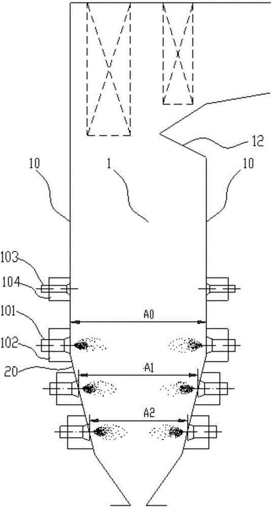
[0044] refer to Figure 5 As shown, this embodiment is basically the same as Embodiment 1, and the difference is that a grade 1 slope section is set in the burner area of ​​the furnace to form a furnace with a variable cross-sectional area (that is, A1


PUM


Abstract

The invention discloses a pulverized coal fired boiler hearth provided with a variable-section combustor area and adapting to flexible peak shaving and belongs to the field of boilers. The heath section area of different combustor layers is not completely the same, the hearth section in the combustor area is gradually enlarged in the flue gas flowing direction, and the specific value of the section area of a section-variable segment of the hearth and the section area of the part, corresponding to a downstream combustor of the hearth, of the hearth ranges from 0.75 to 0.95. The pulverized coal fired boiler solves the above problem existing in a conventional pulverized coal fired boiler hearth type, especially, the single-mill stable combustion capability is achieved, single-mill stable combustion can be achieved on the boiler, and the 20% BMCR oil-feeding-free stable combustion capability is achieved.

Description

technical field [0001] The invention belongs to the field of boilers, in particular to a pulverized coal boiler furnace. Background technique [0002] Large-scale conventional pulverized coal boilers (referring to the pulverized coal boilers whose feeding direction of pulverized coal airflow and combustion accelerant are perpendicular to the flue gas flow in the furnace, corresponding to arch combustion boilers) mainly have П-shaped layout and tower Type layout, there are also a few T-type boilers. The matching combustion methods include wall combustion and tangential combustion, wherein wall combustion includes unilateral wall combustion and hedging combustion, and tangential combustion includes single tangential and double tangential combustion. The existing conventional pulverized coal boilers all adopt the furnace structure with equal cross-sectional area in the combustion area. [0003] For attached figure 1 In the typical П-type layout boiler shown in the figure, th...

Claims


Application Information

Patent Timeline
Patent Type & Authority Applications(China)
IPC IPC(8): F23C3/00F23C7/02
CPCF23C3/00F23C7/02F23C2700/06F23C2900/06041Y02E20/34
Inventor 冉燊铭潘绍成
Owner DONGFANG BOILER GROUP OF DONGFANG ELECTRIC CORP
Why Eureka
Try Eureka