Common-path interference phase microscopy one-time imaging system and method

An interferometric phase and imaging system technology, applied in the research field of biological cell imaging technology, can solve the problems of high professional quality requirements of users, poor sensitivity and stability, multiple optical components, etc., and achieve good practical value, easy operation, and convenient experimental operation. Effect

Active Publication Date: 2017-05-31
JIANGSU UNIV
View PDF7 Cites 10 Cited by
  • Summary
  • Abstract
  • Description
  • Claims
  • Application Information

AI Technical Summary

Problems solved by technology

For example, in the patent CN 104034257 A, a Fizeau-type quasi-common optical path structure synchronous phase-shift interferometry device and method, this technology solves the problem of synchronous phase-shift interference used in the common optical path interference system, so that the existing optical elements in the system The phase measurement error caused by the stress birefringence effect is greatly reduced; another example is the patent CN 102221327 A phase-shift interference microscopy device and method based on Zernike phase contrast imaging. This invention solves the problem that the existing Zernike phase contrast imaging can only be used for Limitations of qualitative observation, while overcoming the technical problems of existing interference microscopy methods such as sensitivity to environmental vibrations, poor stability, high coherent noise, and low lateral resolution
However, these interference microscopy devices require a lot of optical components during use, especially the microscope system, the experimental cost is high, and the requirements for the professionalism of the users are high, so the application threshold is relatively high

Method used


Image

  • Common-path interference phase microscopy one-time imaging system and method

Examples


Embodiment approach

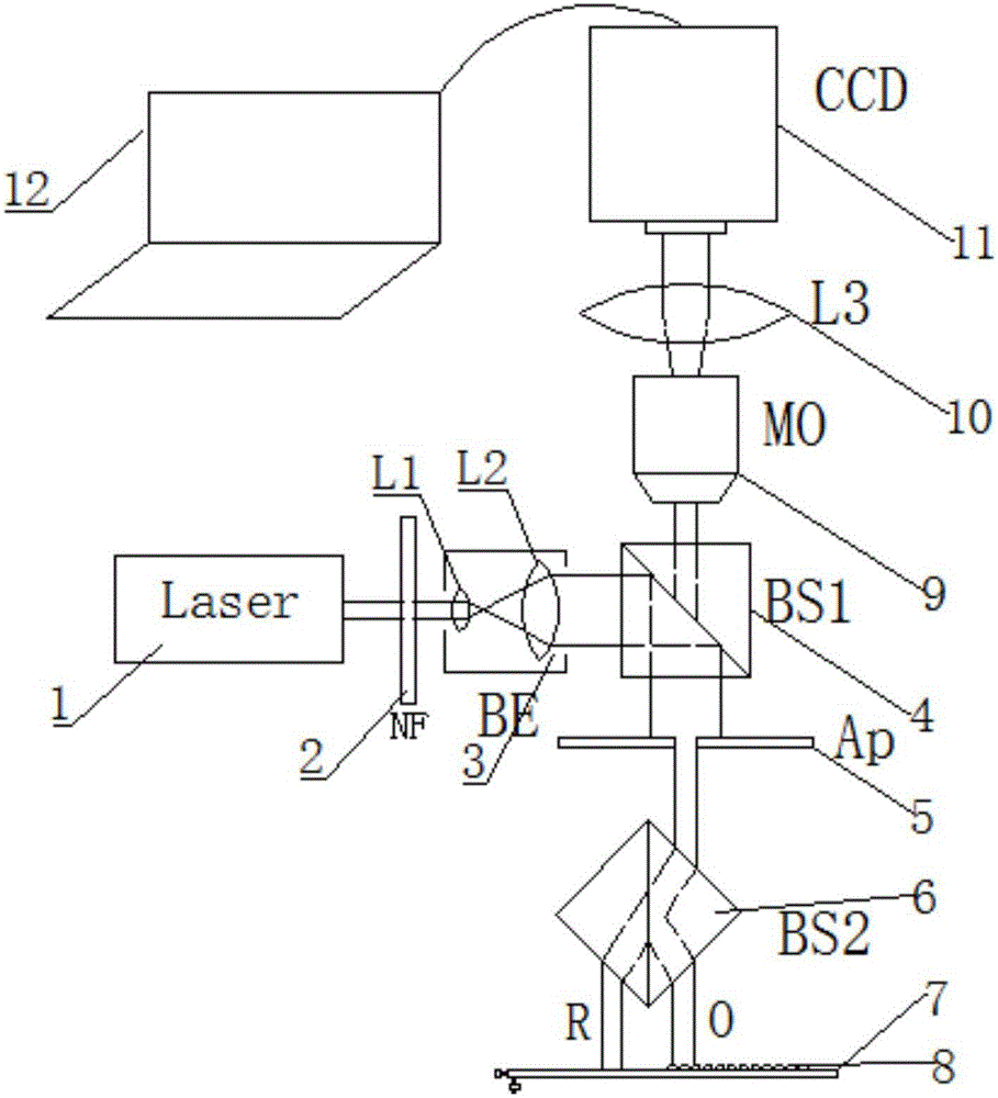
[0028] figure 1 Shown is an embodiment of the common optical path interference phase microscopy primary imaging system and method of the present invention. The common optical path interference phase microscopy primary imaging system includes a laser 1, a neutral adjustable attenuator 2, Beam expander collimator 3, half mirror 4, field stop 5, non-polarizing beam splitting prism 6, reflective stage 7, sample 8, microscope objective lens 9, third lens 10, CCD11 and computer 12.

[0029] The laser 1, the neutral adjustable attenuator 2, the beam expander collimator 3, and the half-mirror 4 are sequentially placed on the same optical path; 7 is placed in the vertical below of half-mirror 4 successively, and described sample 8 is placed on one side on reflective stage 7; The specular surface of described half-mirror 4 is 45 ° with horizontal direction; Used for light splitting The light-splitting layer of the non-polarizing beam-splitting prism 6 is perpendicular to the horizontal...


PUM


Abstract

The invention provides a common-path interference phase microscopy one-time imaging system and method. The common-path interference phase microscopy one-time imaging system comprises a laser, a neutral adjustable damper, a beam-expanding aligner, a half transparent and half reflecting mirror, a field diaphragm, an unpolarized beam splitter prism, a reflecting objective table, a sample, a microscope objective, a third lens, a CCD (Charge Coupled Device) and a computer. The common-path interference phase microscopy one-time imaging system is based on a differential interference light path, the unpolarized beam splitter prism is used for partitioning laser light into two beams of parallel light, namely, object light and reference light, the reflecting objective table is used for reflecting the object light and the reference light totally, the object light and the reference light are combined through the unpolarized beam splitter prism and transmitted in a common-path way, and the combined light is collected by a CCD camera and transmitted to the computer to be displayed after being amplified through the microscope objective. By adopting the common-path interference phase microscopy one-time imaging system and method, the conventional path interference imaging system can be realized by adjusting the angle of the reflecting objective table, including off-axis interference, co-axial interference and slight off-axis interference. The system has a high practical value and a wide application prospect on the aspect of phase microscopy, and can be particularly applied to the field of biological cell morphological identification.

Description

technical field [0001] The invention belongs to the research field of biological cell imaging technology, and in particular relates to a primary imaging system and method of a common optical path interference phase microscope. Background technique [0002] Biological samples under observation, such as living cells, can be treated as transparent, and these cells often appear as phase objects. In order to observe these phase objects clearly, it is common practice to convert phase information into intensity distribution, which leads to the emergence of phase microscopic imaging. In the last ten years, since various quantitative phase microscopy imaging techniques have been continuously proposed, it provides an extremely important research method for studying the tissue structure and dynamic behavior of phase objects similar to biological cells, and Phase microscopic imaging technology basically works by applying the interference principle of light, so this kind of technology c...

Claims


Application Information

Patent Timeline
Patent Type & Authority Applications(China)
IPC IPC(8): G01N21/84G01J9/02
CPCG01J9/02G01J2009/0223G01J2009/0234G01J2009/0269G01N21/84G01N2201/06113
Inventor 季颖张明明王亚伟
Owner JIANGSU UNIV
Why Eureka
Try Eureka