
Intelligent counter system applied to circularly polarized near-field antenna of gold and jewelry industry

A near-field antenna and circular polarization technology, which is applied in the direction of antennas, record carriers used by machines, antenna supports/mounting devices, etc., can solve tag antenna impedance matching, radiation efficiency directional changes, tag reading distance reduction, Destroy system performance and other problems to achieve the effect of reducing system response time and improving flexibility

Active Publication Date: 2017-05-31
刘启达
View PDF4 Cites 5 Cited by
  • Summary
  • Abstract
  • Description
  • Claims
  • Application Information

AI Technical Summary

Problems solved by technology

[0006] On the other hand, when the electronic tags attached to gold jewelry items work on the surface of metal objects such as yellow silver rings or necklaces, etc., after the electromagnetic waves reach the target tag, they are emitted back by a small part of the tagged antenna metal surface, and most of the electromagnetic waves will be An electromagnetic radiation field is formed near the metal surface; the magnetic field part of the field only has a tangential component but no normal component, and the magnetic flux generated on the metal surface causes an induced eddy current; according to Lenz's law, the induced eddy current radiates to the reader The opposite effect of the field, which causes the magnetic field to decay rapidly on the metal surface, so that the minimum power threshold required to activate the chip cannot be reached, resulting in the tag being unable to be read, that is, the missing reading of the monitored item
In addition, the energy loss caused by the electromagnetic radiation caused by the metal will also cause additional parasitic capacitance, which will cause the detuning of the electromagnetic coupling system between the reader and the tag antenna, and destroy the performance of the system, that is, the response frequency of the electronic tag and the design frequency. Offset
The electromagnetic environment of the electronic tags working in the 860-960MHz frequency band mentioned in the present invention and the gold or silver rings attached to the counter is particularly complicated, that is, the energy reflected by the metal objects and the tags and Interference (coupling and spurious) is formed between the readers, which leads to changes in the electromagnetic parameters such as impedance matching, radiation efficiency, and directivity of the tag antenna, and the reading distance of the tag decreases rapidly, and it is even difficult to be read by the reader. Pick

Method used


Image

  • Intelligent counter system applied to circularly polarized near-field antenna of gold and jewelry industry
  • Intelligent counter system applied to circularly polarized near-field antenna of gold and jewelry industry
  • Intelligent counter system applied to circularly polarized near-field antenna of gold and jewelry industry

Examples


Embodiment 1

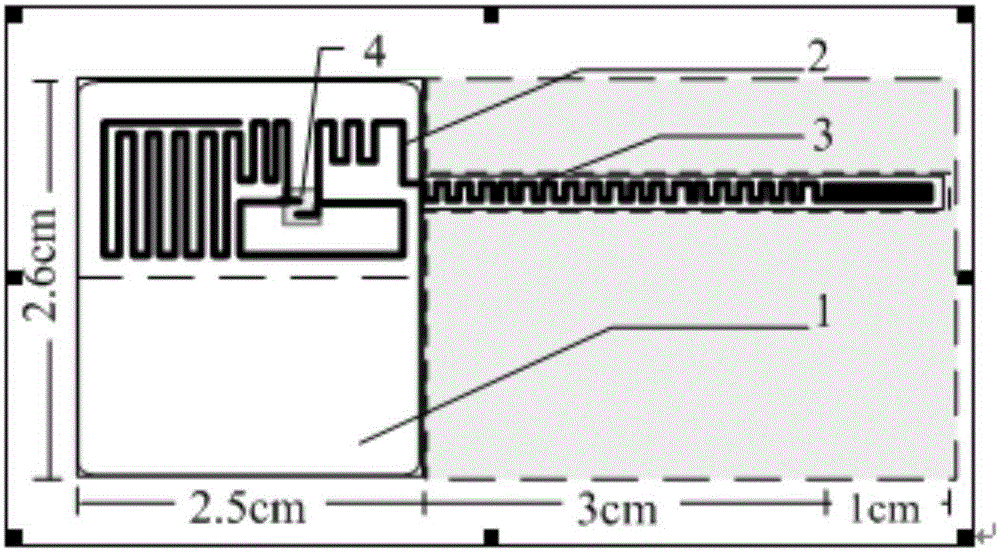
[0039] Such as figure 1 As shown, the electronic tag used in this embodiment is a foldable snake-shaped load UHF RFID electronic tag, which is an existing jewelry item label standard (DIN 58681-1 Bb.1-1981) in the gold jewelry industry. The electromagnetic information storage function is added on the basis, that is, the RFID antenna structure (the non-foldable second substrate part 2 and the foldable second substrate part 3) is fabricated on the foldable first substrate by an etching method or a screen printing process. Material part 1, and on the second substrate part 2, the chip label is fixed on the part 2 through RFID chip binding equipment, and finally double-sided adhesive is applied on the surface of part 1 for post-adhesion purposes. In order to facilitate quantitative production, the first base material part 1 is divided into two parts, white base and gray base, and the cut part of the gray base part is shown by a dotted line, and the label does not include the part o...

Embodiment 2

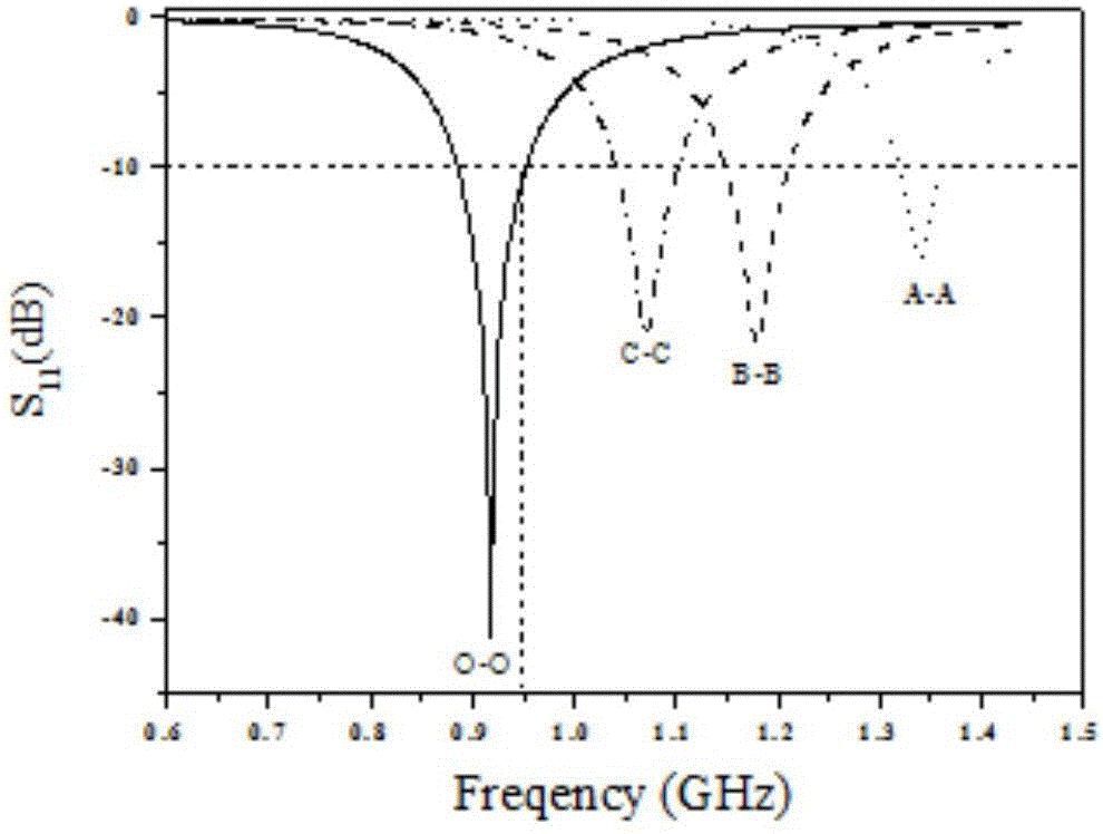
[0048] In this embodiment, the return loss test results of the fixed near-field antenna using a vector network analyzer are as follows: Figure 10 shown. The fixed near-field antenna can have a good reading rate for tags with a center resonant frequency near 915MHz (903MHz-925MHz); when the response frequency band of the tag frequency is greater than 925MHz, the performance of the antenna decreases rapidly. The designed antenna is used in conjunction with the design of the foldable serpentine load UHF electronic tag proposed by the present invention, which can meet the different requirements of jewelry product tags on tag performance before, during and after sales. Before sales, the real-time inventory function is required for the items placed in the counter; during the sales process, it is necessary to meet the data collection and monitoring functions of the operator for the items to leave the placement position and move to the upper surface position of the counter, so as to ...


PUM

PropertyMeasurementUnit
Thicknessaaaaaaaaaa
Thicknessaaaaaaaaaa
Widthaaaaaaaaaa

Abstract

The invention elates to an intelligent counter system applied to a circularly polarized near-field antenna of the gold and jewelry industry, which comprises foldable snake-shaped load ultrahigh frequency electronic tags attached to each gold and jewelry product, a fixed near-field antenna installed below a counter in an array mode, a multipath signal acquiring device connected to the fixed near-field antenna and a real-time inventory checking workstation connected with the multipath signal acquiring device, and is characterized in that the real-time inventory checking workstation performs control on the fixed near-field antenna installed below the counter in an array mode, realizes read-write control on the electronic tags attached to objects displayed on the intelligent counter, and stores the information, which comprises stores to which the objects belong, intelligent counter and antenna position information of the belonging stores, whether the objects leave the corresponding counter or not, the starting and ending time of departure of the objects from the counter, and whether the objects are normally sold or not, of the monitored objects to the real-time inventory checking workstation; and the real-time inventory checking workstation can work independently in a local database management system and can also collaborate with a cloud database management system.

Description

technical field [0001] The present invention relates to the application of ultra-high frequency electronic tags (UHF-smart RFID, 860-960MHz) in the Internet of Things, in particular to an intelligent counter system for circularly polarized near-field antennas used in the gold and jewelry industry, for gold / jewelry to be sold The electronic tag of the item and its antenna reading and writing system can perform online monitoring and real-time inventory functions on the items placed in the smart counter, and can analyze customer behavior. Background technique [0002] Radio frequency identification (RFID) is a non-contact automatic identification technology realized by radio frequency technology. The RFID system is generally composed of two main parts: an electronic tag (tag) and a reader (reader); through a coded tag and an antenna attached to the tag, the reader and the tag perform non-contact high-speed data transmission and communication. Complete the automatic identificat...

Claims


Application Information

Patent Timeline
IPC IPC(8): G06K7/00G06K19/077H01Q1/22H01Q1/36H01Q1/38H01Q1/50H01Q19/10
Inventor 刘启达
Owner 刘启达
Learn More