Microgrid current conversion and energy storage apparatus and energy management method therefor

An energy storage device and energy management technology, which is applied in circuit devices, battery circuit devices, energy reserves, etc., and can solve the unfavorable unified management of energy in decentralized arrangement, the influence of local microgrid voltage stability, and poor output common-mode voltage characteristics, etc. problem, to achieve the effect of rich functions, balanced power fluctuation, and low switching loss

Pending Publication Date: 2017-05-31
FUYANG NORMAL UNIVERSITY
View PDF4 Cites 10 Cited by
  • Summary
  • Abstract
  • Description
  • Claims
  • Application Information

AI Technical Summary

Problems solved by technology

Most of the current low-power photovoltaic systems use non-isolated inverter structures, such as single-phase full-bridge inverters. This type of non-isolated inverter has disadvantages such as poor output common-mode voltage characteristics and high leakage current to ground. The average number is low, harmonics are injected to the grid side, and the filter device is bulky
In addition, the access of large-scale distributed photovoltaic power generation systems also brings challenges to grid energy management. Intermittent distributed power sources affect the voltage stability of local micro-grids. The role of power supply peak shaving and valley filling requires the arrangement of energy storage devices in the microgrid
Most of the energy storage devices of existing small and medium power grid-connected systems are installed on the side of the DC bus, with small capacity, multi-level energy conversion, and low efficiency. At the same time, the decentralized arrangement is not conducive to unified energy management

Method used


Image

  • Microgrid current conversion and energy storage apparatus and energy management method therefor
  • Microgrid current conversion and energy storage apparatus and energy management method therefor
  • Microgrid current conversion and energy storage apparatus and energy management method therefor

Examples


Embodiment approach 1

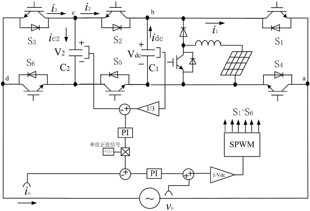
[0023] Implementation Mode 1: In this implementation mode, taking the working process of a six-switch seven-level single-phase inverter as an example, the schematic diagram of the circuit structure is as follows: figure 1 As shown, the working process of the device converting sunlight into electric energy, inverting and connecting to the grid is described. Assuming that the output voltage of the photovoltaic array is Vpv, it is boosted to Vdc after passing through the maximum power tracking circuit. According to the on and off states of the power switching devices in the inverter, the inverter can operate in the following modes:

[0024] Define the switch function as

[0025]

[0026] then if figure 1 The voltage of each node in can be expressed by the switch function as

[0027]

[0028] Then, the inverter output AC side voltage can be expressed as

[0029] v ad =v ab +v bc v cd =(S 1 -S 2 )V 1 +(S 2 -S 3 )V 2 (3)

[0030] In the same way, the switching f...

Embodiment approach 2

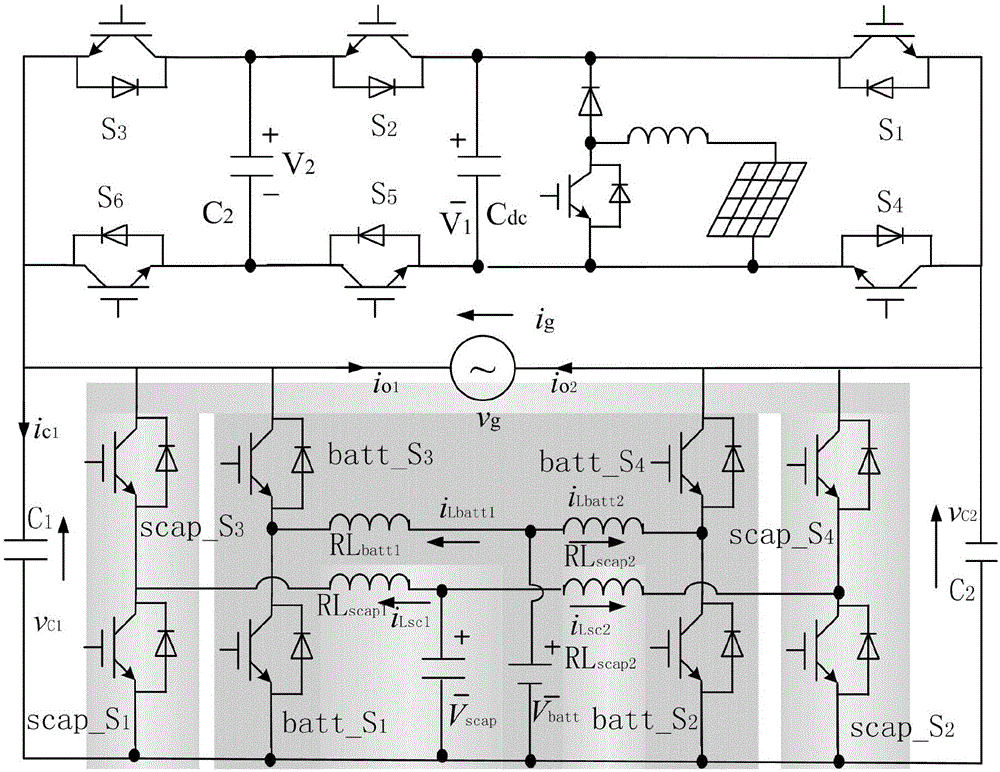
[0038] Embodiment 2: In this embodiment, the control method of the energy storage device and its boost DC / AC converter is analyzed. The energy storage device adopts the hybrid energy storage form of battery pack and super capacitor. The charging and discharging time constant of the battery pack is large, and the service life is seriously reduced as the number of charging and discharging increases. The power balance of the low-frequency part of the load changes. Compared with batteries, supercapacitors charge and discharge faster, have higher efficiency and longer life, and are responsible for the power balance of high-frequency parts of load changes. The circuit structure diagram is as follows figure 2As shown, the structure of the boost DC / AC converter connected to the battery pack and the supercapacitor is exactly the same. Taking the battery pack and its DC / AC converter as an example for analysis, the power switch devices batt_S1, batt_S3 and RLbatt1 constitute the left B...

Embodiment approach 3

[0058] Embodiment 3: In this embodiment, the energy control strategy and management method in the present invention are analyzed. The segmental droop control of the DC bus voltage is adopted to determine the relationship between the DC bus voltage and the charging and discharging of the energy storage device, and the action of the energy storage device is controlled to balance the power fluctuation of the system. Combined with the actual system load power, photovoltaic array power, grid-connected inverter rated power, and energy storage device capacity, set 5 segmentation points for the DC bus voltage value (corresponding to Vth1>Vth2>Vth3>Vth4>Vth5), and the corresponding There will be five working modes, which will be analyzed in detail below.

[0059] System working mode 1: When Vth1


PUM


Abstract

The invention relates to the fields of new energy power generation and energy management thereof, specifically to a microgrid current conversion and energy storage apparatus and an energy management method therefor. The microgrid current conversion and energy storage apparatus comprises a six-switch seven-level single-phase inverter unit, a bidirectional DC/AC converter unit for a storage battery, a bidirectional DC/AC converter unit for a supercapacitor, a micro current converter energy storage apparatus control and energy management unit, a photovoltaic MPPT unit, a storage battery charging-discharging management unit, a supercapacitor charging-discharging management unit and a load management unit. By adoption of the microgrid current conversion and energy storage apparatus and the energy management method therefor, photovoltaic energy can be converted into electric energy to be connected to a power grid; power fluctuation balance of the system through peak-load shifting can be realized by the energy storage apparatus according to the energy flowing condition of the system; by adoption of the six-switch seven-level single-phase inverter, the apparatus is less in required power switching devices, low in switching loss, and high in output electric energy quality; the energy storage apparatus adopts the bidirectional DC/AC converters, so that compared with the conventional current converter, the energy storage apparatus has the advantages of less switching devices, wide voltage output range, simple SPWM modulation and the like; and therefore, the energy storage apparatus has wide application prospect in the microgrid application field.

Description

technical field [0001] The invention relates to the field of new energy power generation and its energy management, in particular to a micro-grid variable current energy storage device and its energy management method. Background technique [0002] With the strong support of national policies in recent years, more and more distributed power generation such as household photovoltaic power generation, community photovoltaic power generation, and enterprise office building photovoltaic power generation has been incorporated into the public grid. Although the use of these new energy sources is conducive to low-carbon emission reduction and increased economic benefits, they are obviously intermittent and unstable due to environmental conditions. To impact and interfere. Microgrid technology is an ideal means to solve the above contradictions. Microgrid is a small power generation and distribution system that can realize self-control and management. It usually includes distribute...

Claims


Application Information

Patent Timeline
Patent Type & Authority Applications(China)
IPC IPC(8): H02J3/38H02J3/32H02J7/34
CPCH02J3/32H02J3/385H02J7/345Y02E10/56Y02E70/30
Inventor 王静董苏于立志王诗兵韩波王戴木王峰
Owner FUYANG NORMAL UNIVERSITY
Why Eureka
Try Eureka