
Oxygen-enriched combustion boiler system for circulating fluidized bed

A technology of circulating fluidized bed and oxygen-enriched combustion, which is applied in the direction of fluidized bed combustion equipment, fuel for combustion in a molten state, and combustion methods, etc. It can solve the problems of declining economic efficiency, restricting commercial applications, and increasing boiler island investment and operating costs and other issues, to achieve the effect of reducing initial investment and operating costs, saving denitrification costs, and reducing floor space

Active Publication Date: 2017-06-13
INST OF ENGINEERING THERMOPHYSICS - CHINESE ACAD OF SCI
View PDF5 Cites 8 Cited by
  • Summary
  • Abstract
  • Description
  • Claims
  • Application Information

AI Technical Summary

Problems solved by technology

However, the existing oxygen-enriched combustion technology only replaces the nitrogen in the air with a high-concentration CO 2 The volume share of oxygen in the tail flue gas varies little (21% to 27%), so compared with conventional air combustion units, the investment in the boiler body (furnace and tail heating surface) is basically unchanged, but due to the increase The investment and operating costs of the air separation oxygen generation system and flue gas recirculation system, boiler island will increase significantly, which will reduce the economic efficiency of the whole plant by about 8% to 12%, which is very important for coal-fired power stations. It is unacceptable, and it is also the main reason restricting the large-scale commercial application of existing oxyfuel combustion technology

Method used


Image

  • Oxygen-enriched combustion boiler system for circulating fluidized bed

Examples


Embodiment Construction

[0028] In order to make the object, technical solution and advantages of the present invention clearer, the present invention will be further described in detail below in conjunction with specific embodiments and with reference to the accompanying drawings. The drawings accompanying this description are simplified and used for illustration purposes. The number, shape and size of the components shown in the drawings can be modified according to the actual situation, and the configuration of the components may be more complicated. Other aspects of practice or application can also be carried out in the present invention, and various changes and adjustments can be made without departing from the defined spirit and scope of the present invention.

[0029] According to the basic idea of ​​the present invention, to overcome the disadvantages of poor economic efficiency of the existing oxygen-enriched combustion technology, a circulating fluidized bed oxygen-enriched combustion boiler...


PUM


Abstract

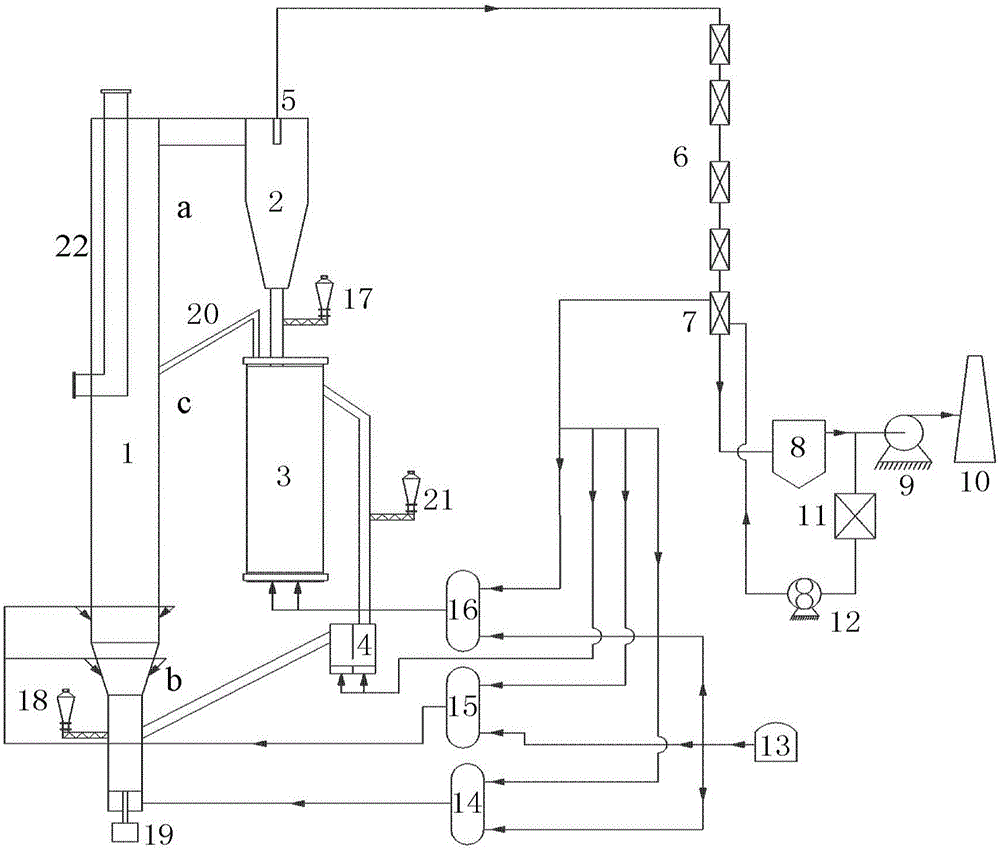
An oxygen-enriched combustion boiler system for a circulating fluidized bed comprises a hearth, a cyclone separator, an externally-arranged combustion chamber, a tail smoke flue and an air supply unit. An outlet of the hearth is connected to the cyclone separator and used for outputting smoke gas containing circulating materials from the hearth; after the smoke gas containing the circulating materials is separated by the cyclone separator, the circulating materials enter the externally-arranged combustion chamber from an outlet of the lower portion of the cyclone separator, and the smoke gas portion enters the tail smoke flue from an outlet of the upper portion of the cyclone separator; and the circulating materials are input into the externally-arranged combustion chamber by the cyclone separator, fluidizing air is input into the externally-arranged combustion chamber by the air supply unit, and an outlet of the externally-arranged combustion chamber is connected to the inlet end of the hearth. According to the oxygen-enriched combustion boiler system for the circulating fluidized bed, the mode that burning is conducted on the inlet under the high oxygen concentration is adopted, the sizes of a boiler body and an auxiliary machine are greatly reduced, initial investment and operating cost of a boiler can be reduced, and the occupied area of a boiler island is reduced.

Description

technical field [0001] The invention relates to combustion equipment, in particular to a circulating fluidized bed oxygen-enriched combustion boiler system. Background technique [0002] The greenhouse gas CO produced by the burning of fossil fuels 2 It has had a serious impact on the global climate and environment. The power station industry occupies an important position in the use of fossil fuels, and is dominated by coal-fired power stations, accounting for more than 40% of the power station industry. Therefore, it is necessary to find a CO suitable for coal-fired power plants 2 Capture technical solutions. in the existing CO 2 Among capture technologies, oxyfuel combustion technology (also known as O 2 / CO 2 Flue gas recirculation combustion technology) is a large-scale industrial application of coal-fired CO 2 One of the capture technologies. This technology uses pure oxygen and circulating flue gas instead of air as the oxidant to enter the boiler for combusti...

Claims


Application Information

Patent Timeline
IPC IPC(8): F23C10/10F23C10/18F23L7/00
CPCF23C10/10F23C10/18F23C2206/10F23L7/00F23L7/007Y02E20/34
Inventor 李诗媛李伟张啸天徐明新柳殿斌
Owner INST OF ENGINEERING THERMOPHYSICS - CHINESE ACAD OF SCI
Learn More