Anaerobic pyrolysis treatment system and method for garbage

A treatment system and pyrolysis technology, applied in the field of waste treatment, can solve the problems of easy adhesion to the wall and shaft of the reaction tank, the inability of the equipment to run stably for a long time, and the large energy consumption of cooling fluidized steam, etc. The effect of a small number of equipment and a low total smoke emission

Pending Publication Date: 2017-06-13
BEIJING AEROSPACE PETROCHEM TECH & EQUIP ENG CORP LTD
View PDF6 Cites 5 Cited by
  • Summary
  • Abstract
  • Description
  • Claims
  • Application Information

AI Technical Summary

Problems solved by technology

However, in the anaerobic pyrolysis process of garbage, for the indirect heating process, the pyrolysis device indirectly heats the garbage through the heat source at high temperature, so that the garbage is thermally cracked, the heating speed of the garbage is slow, the treatment efficiency is not high, and the temperature in the equipment is not uniform. After the waste heats up and turns into a molten state, it is extremely easy to stick to the wall and shaft of the reaction tank, causing coking, which not only affects heat transfer, but also blocks the pipeline, making it impossible to effectively pyrolyze. At the same time, the coking products cannot be removed. The equipment cannot run stably for a long time; for the double-tower fluidized bed pyrolysis process, the pyrolysis device of the process is a fluidized bed, using steam or purified gas as the fluidization medium, and for the pyrolysis process using steam as the fluidization medium, The generation and cooling of fluidized steam consumes a lot of energy. For the pyrolysis process that uses purified gas as the fluidization medium, the dust removal, cooling, and pressurization of the gas consume a lot of energy. The energy consumption of the existing process is high, and the overall thermal efficiency is not high.

Method used


Image

  • Anaerobic pyrolysis treatment system and method for garbage
  • Anaerobic pyrolysis treatment system and method for garbage

Examples


Embodiment Construction

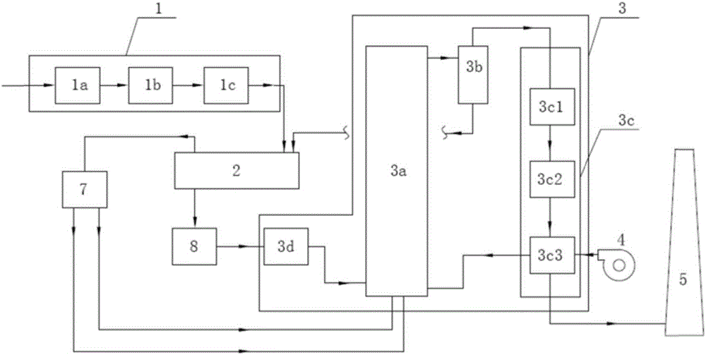
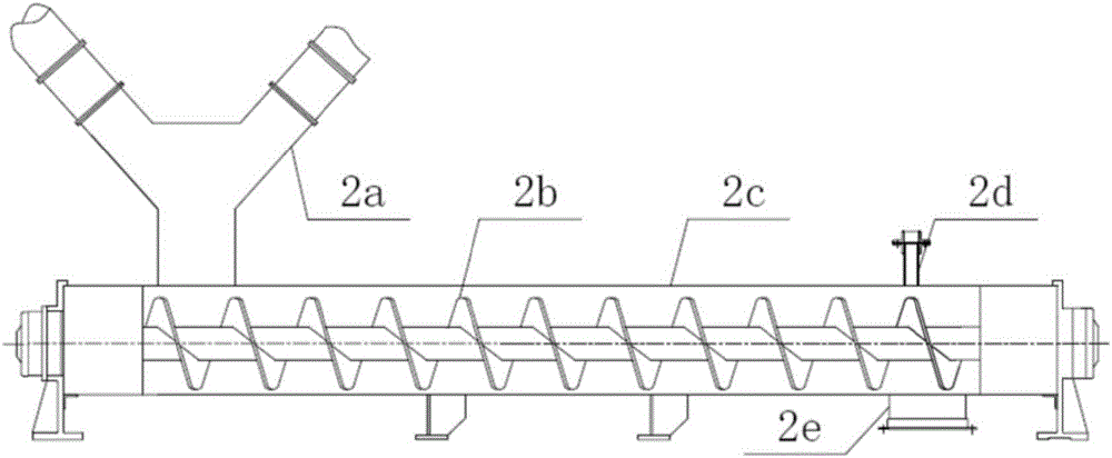
[0031]An anaerobic pyrolysis treatment system for garbage, comprising a pretreatment unit 1, a pyrolysis device 2, a combustion unit 3, a purification device 7, and an intermediate silo 8, wherein the pretreatment unit 1 includes a sorting unit 1a, a crushing unit 1b, The drying unit 1c, and the sorting unit 1a, the crushing unit 1b, and the drying unit 1c are connected in series in sequence, the drying unit 1c is connected to the pyrolysis device 2, and the pyrolysis device 2 is respectively connected to the purification device 7 and the intermediate silo 8, and the combustion unit 3 includes Furnace 3a, gas-solid separation device 3b, waste heat recovery unit 3c, feeder 3d, and waste heat recovery unit 3c includes air preheater 3c3, economizer 3c2, superheater 3c1, purification device 7 through two pipelines and combustion The furnace 3a in the unit 3 is connected, and the intermediate feed bin 8 is connected with the feeder 3d of the solid heat carrier furnace, and in the so...


PUM


Abstract

The invention discloses an anaerobic pyrolysis treatment system for garbage. The Anaerobic pyrolysis treatment system comprises a pyrolysis device, a solid thermal carrier furnace, a purification device and an intermediate bunker, wherein a pretreatment unit comprises a separation unit, a crushing unit and a drying unit; the separation unit, the crushing unit and the drying unit are sequentially connected in series; the drying unit is connected with the pyrolysis device; the pyrolysis is connected with the purification device and the intermediate bunker respectively; the solid thermal carrier furnace comprises a hearth, a gas-solid separation device, a waste heat recycling unit and a return feeder; the waste heat recycling unit comprises an air preheater, an economizer and an over heater; the purification device is connected with the hearth of a combustion unit through two pipelines; the intermediate bunker is connected with the return feeder of the solid thermal carrier furnace; in the solid thermal carrier furnace, the return feeder is connected with the hearth; the hearth is connected with the gas-solid separation device; the gas-solid separation device is connected with the pyrolysis device and the waste heat recycling unit respectively; the waste heat recycling unit comprises the over heater, the economizer and the air preheater.

Description

technical field [0001] The invention belongs to the technical field of garbage treatment, and in particular relates to an anaerobic pyrolysis treatment system and method for garbage. Background technique [0002] In the past 20 years, with the acceleration of urbanization in our country, a large amount of municipal waste with increasing output has become an increasingly serious threat to the ecological environment of the city and its surroundings. The commonly used sanitary landfill technology and composting technology have been difficult to cope with the reality of high waste production. The government is changing this situation by increasing the proportion of waste incineration. However, waste incineration will bring secondary environmental pollution problems such as dioxin emissions, causing people Huge panic. Therefore, the key to solving domestic waste pollution is to update waste disposal technology. [0003] Garbage pyrolysis treatment technology is the process of b...

Claims


Application Information

Patent Timeline
Patent Type & Authority Applications(China)
IPC IPC(8): F23G5/027F23G5/14F23G5/44
CPCF23G5/027F23G5/14F23G5/444F23G2201/302
Inventor 张彦军宋小飞杜闰萍钱永康
Owner BEIJING AEROSPACE PETROCHEM TECH & EQUIP ENG CORP LTD
Why Eureka
Try Eureka