
Photoelectric composite cable

An optoelectronic integrated cable and cable core technology, which is applied to insulated cables, communication cables, bendable cables, etc., can solve the problems of loose optoelectronic integrated cable structure, low production efficiency, and blocked optical paths, so as to improve the strain screening strength, improve the use of The effect of improved reliability and excellent bending properties

Inactive Publication Date: 2017-06-13
上海传输线研究所
View PDF4 Cites 2 Cited by
  • Summary
  • Abstract
  • Description
  • Claims
  • Application Information

AI Technical Summary

Problems solved by technology

Although the photoelectric integrated cable with this structure has the characteristics of softness and repeatability, due to its large outer diameter and heavy weight, it cannot be quickly and repeatedly retracted by a single person, and cannot meet the requirements of mobility and convenience.
Since the conventional photoelectric integrated cable uses ordinary G.652 single-mode optical fiber, the bending radius is relatively large. In actual use, when the bending radius is small, the additional attenuation of the optical fiber will increase. In severe cases, the optical fiber will be broken and the optical path will be blocked. The phenomenon
During the drawing and screening process of conventional optical fibers, micro-cracks will appear on the surface. In the actual use process, the micro-cracks on the surface of the optical fiber will be deteriorated due to the erosion of water molecules in the air. Life and Reliability
Conventional optoelectronic integrated cable usually divides optoelectronic integrated cable core stranding, reinforced layer armor and outer sheath extrusion into three or two processes for processing respectively. The production efficiency is low, and the structure of optoelectronic integrated cable is relatively loose. Unstable performance and poor reliability in the use environment

Method used


Image

  • Photoelectric composite cable
  • Photoelectric composite cable
  • Photoelectric composite cable

Examples


Embodiment 1

[0039] The optical fiber secondary coating extruder is selected, and a tight sleeve layer is uniformly coated on the outside of the optical fiber at a line speed of 40m / min at a tension of 0.5N and an extrusion temperature of 130°C to 200°C. When the optical fiber is a bending loss insensitive single-mode optical fiber with a carbon coating layer, the diameter of the optical fiber is 0.245mm, the strain screening of the optical fiber is 2%, the static fatigue resistance index N is 100, and the material of the tight sleeve layer is preferably flame-retardant polyurethane , the outer diameter of the tight sleeve layer is 0.4mm, and then cooled by a water tank, the cooling temperature of the water tank is between 30°C and 40°C, and the mold adopts a squeeze tube type to make a tight sleeve optical fiber with an outer diameter of 0.4mm;

[0040] Then choose a high-temperature extruder, under the condition that the take-up and take-off line tension is 1.0N, and the extrusion tempera...

Embodiment 2

[0043] The optical fiber secondary coating extruder is selected, and a tight sleeve layer is uniformly coated on the outside of the optical fiber at a line speed of 70m / min at a tension of 1.0N and an extrusion temperature of 180°C to 250°C. When the optical fiber is a multi-mode optical fiber, the diameter of the optical fiber is 0.3mm, and the strain of the optical fiber is 1%. The material of the tight jacket layer is preferably a thermoplastic polyester elastomer Hytrel, and the outer diameter of the tight jacket layer is 0.6mm, and then passes through the water tank Cooling, the cooling temperature of the water tank is between 40°C and 60°C, and the mold adopts extrusion type to make a tight-sleeved optical fiber with an outer diameter of 0.6mm;

[0044] Then choose a high-temperature extruder, under the condition that the winding tension is 5.0N and the extrusion temperature is between 280°C and 380°C, a layer of insulating layer is uniformly extruded outside the conducto...

Embodiment 3

[0047] The optical fiber secondary coating extruder is selected, and a tight sleeve layer is uniformly coated on the outside of the optical fiber at a line speed of 100m / min at a tension of 0.8N and an extrusion temperature of 180°C to 250°C. When the optical fiber is a bending loss insensitive single-mode optical fiber provided with a coating layer, the diameter of the optical fiber is 0.4mm, and the strain screening of the optical fiber is 1%. The material of the tight jacket layer is preferably nylon, and the outer diameter of the tight jacket layer is 0.8mm. Then it is cooled in a water tank, the cooling temperature of the water tank is between 30°C and 40°C, and the mold adopts a squeeze tube type to make a tight-sleeved optical fiber with an outer diameter of 0.8mm;

[0048] Then choose a high-temperature extruder, under the condition that the take-up and take-off line tension is 3.0N, and the extrusion temperature is between 130°C and 200°C, a layer of insulating layer i...


PUM

PropertyMeasurementUnit
diameteraaaaaaaaaa
thicknessaaaaaaaaaa
distanceaaaaaaaaaa

Abstract

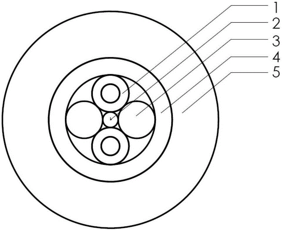
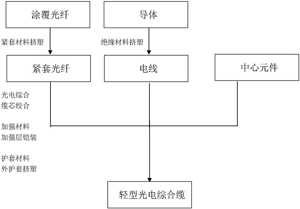
The invention discloses a photoelectric composite cable. The photoelectric composite cable comprises a cable core, a reinforcing layer and an outer sheath, which are arranged in sequence from inside to outside, wherein the cable core is of a four-core symmetrical interval stranded structure formed by stranding two tight buffered optical fibers with the same outer diameter and two electric wires on one central element; each tight buffered optical fiber comprises an optical fiber provided with a coating layer and a tight buffered layer; the diameter of each optical fiber is 0.2mm to 0.4mm; meanwhile, the invention further discloses a method for preparing the photoelectric composite cable; and the method comprises the following three steps: preparing the tight buffered optical fibers, preparing the electric wires and stranding the photoelectric composite cable core, and armoring a reinforcing layer and extruding the outer sheath. The photoelectric composite cable provided by the invention is novel in structural design, reasonable in material selection and stable and reliable in product performance; the outer diameter and weight of the photoelectric composite cable are extremely reduced; special requirements of rapidly, conveniently and repeatedly deploying and retracting the cable by a single person are met; meanwhile, a machining manner of molding in one step is adopted, so that machining procedures are effectively reduced and the production efficiency is improved; the structure of the photoelectric composite cable is more compact and performances are stable and reliable.

Description

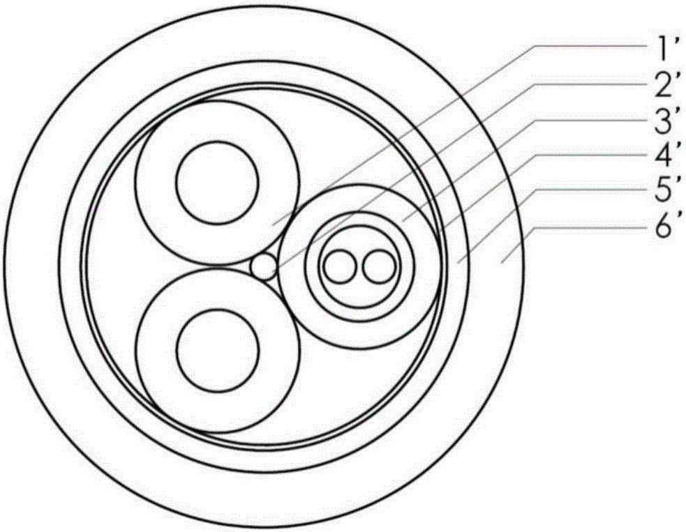
technical field [0001] The invention belongs to the field of optical cables, and relates to a light-weight photoelectric composite cable, in particular to a light-weight photoelectric composite cable suitable for repeated retraction by a single person. Background technique [0002] At present, many users have further increased demand for light-weight photoelectric integrated cables that are small in size, light in weight, and can be quickly and repeatedly retracted by a single person. , cannot meet the special requirements of the light-weight photoelectric composite cable, and cannot be quickly and conveniently retracted and used repeatedly in the field, vehicle, ship-borne and airborne application environments, so it is necessary to invent a light-weight photoelectric composite cable. [0003] Conventional photoelectric integrated cables currently on the market, such as figure 1 As shown, it is composed of wire 1', central element 2', fiber unit 3', polyester film tape 4',...

Claims


Application Information

Patent Timeline
Patent Type & Authority Applications(China)
IPC IPC(8): H01B7/04H01B7/18H01B7/282H01B11/22H01B13/14H01B13/02H01B13/24
CPCH01B7/04H01B7/18H01B7/282H01B11/22H01B13/02H01B13/14H01B13/24
Inventor 杨国发
Owner 上海传输线研究所
Learn More