Push rod single-oscillating-tooth transmission opposite-column double-cylinder internal combustion engine

A push rod single movable tooth, movable tooth transmission technology, applied in the direction of machines/engines, mechanical equipment, etc., can solve many problems, only part of the output power, the decline of the thermal energy utilization rate of the internal combustion engine, and the low thermal energy utilization rate of the internal combustion engine. Achieve the effect of eliminating eccentric wear phenomenon, simple structure and reducing maintenance cost

Inactive Publication Date: 2017-06-20
雷敬汉
View PDF4 Cites 0 Cited by
  • Summary
  • Abstract
  • Description
  • Claims
  • Application Information

AI Technical Summary

Problems solved by technology

[0003] 1. Since the internal combustion engine uses the connecting rod crankshaft to convert the reciprocating motion of the piston into a circular motion, when the compression stroke of the cylinder ends, that is, at the top dead center of the expansion power stroke, the mixture in the cylinder is burned to make the pressure in the cylinder maximum and produce the strongest Thrust, but at this time in the crank-link mechanism, the crankshaft and the connecting rod are in a straight line, that is, the moment arm is zero, that is, there is no power output at this time, that is, no work is done to the outside; and the circular motion of the crankshaft will inevitably cause the connecting rod connected to the crankshaft to The included angle changes, the power is widely distributed, and only part of the power can be transmitted, so the crankshaft and connecting rod mechanism makes the heat utilization rate of the internal combustion engine very low;
[0004] 2. The angle between the connecting rod and the moving direction of the piston will cause a certain amount of friction between the piston and the inner wall of the cylinder block. The larger the angle between the connecting rod and the moving direction of the piston, the greater the friction. The friction force generated by the wall is uneven, so after the piston moves at high speed for a long time in the cylinder, it is easy to cause eccentric wear, which will damage the inner wall of the cylinder or the piston and cause air leakage, so that the heat utilization rate of the internal combustion engine will decrease. The problem that has not been solved since the use of the rod internal combustion engine;
[0005] 3. The upper part of the crankshaft connecting rod internal combustion engine body where the cylinder is installed and the lower part where the crankshaft and crankcase are installed are combined for integral casting. Because the coordinated operation of the various components in the crankshaft connecting rod internal combustion engine requires the crankshaft connecting rod internal combustion engine body The design of each part of the internal combustion engine has extremely high precision, especially the strict requirements on the position, shape and size of each cylinder and crankshaft in the internal combustion engine body, which will inevitably lead to the difficulty of processing and producing high-precision integrally cast crankshaft connecting rod internal combustion engine body Because the body of the internal combustion engine is formed by integral casting, once the damage of the body of the internal combustion engine is caused by a certain cylinder damage, then the whole body of the internal combustion engine is just scrapped and needs to be replaced, so that other components such as crankcases that are not damaged in the body of the internal combustion engine are also abandoned. cause waste;
[0006] 4. The cylinders of the internal combustion engine and the crankshafts corresponding to the cylinders are arranged in a straight line. The linear arrangement of the crankshafts will inevitably lead to an increase in the volume of the internal combustion engine, which will also increase the volume of the transmission components in the internal combustion engine, and the various components in the internal combustion engine will increase accordingly. The result of the increase is that the friction force when the internal combustion engine is running also increases, which means that the energy consumption of the internal combustion engine also increases when the internal combustion engine is running.

Method used


Image

  • Push rod single-oscillating-tooth transmission opposite-column double-cylinder internal combustion engine
  • Push rod single-oscillating-tooth transmission opposite-column double-cylinder internal combustion engine
  • Push rod single-oscillating-tooth transmission opposite-column double-cylinder internal combustion engine

Examples


Embodiment 1

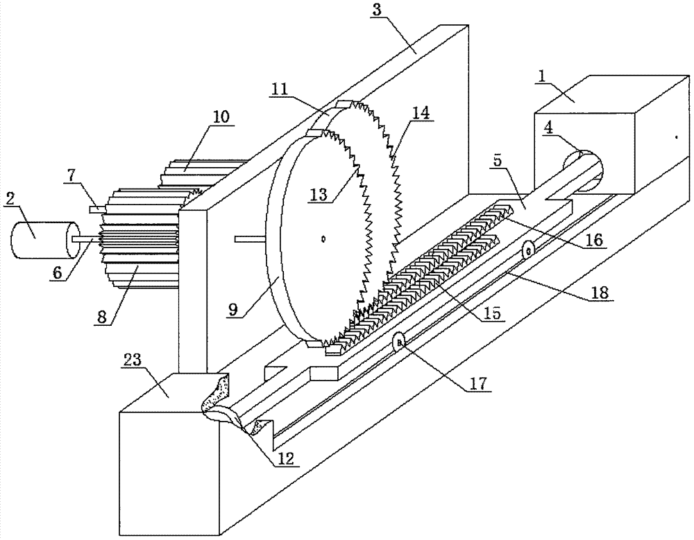
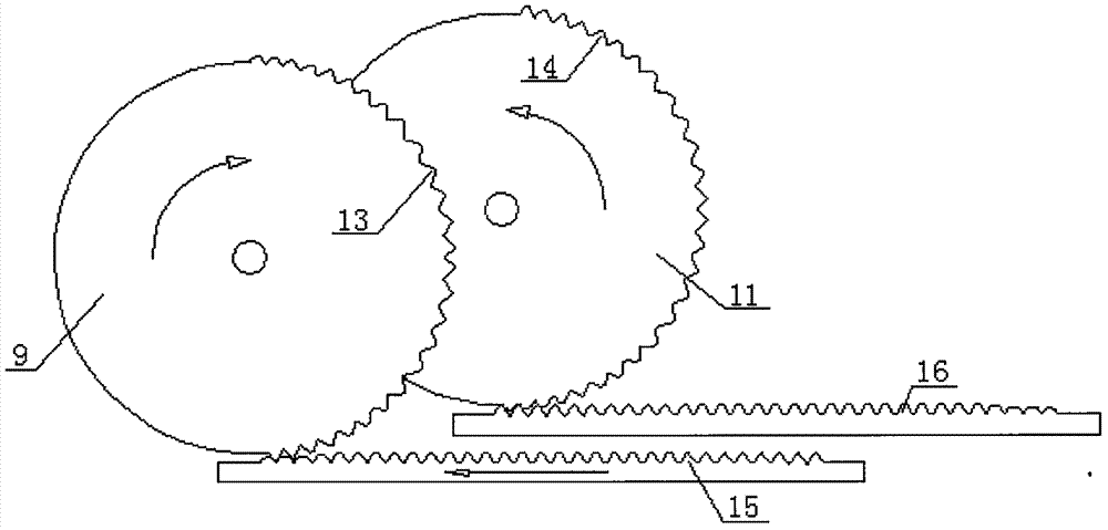
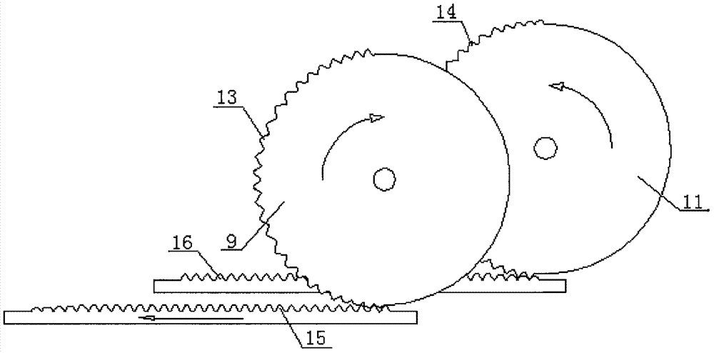
[0023] Example as figure 1 As shown, the push rod movable tooth transmission paired twin-cylinder internal combustion engine of the present embodiment includes a cylinder, a transmission shaft 2 and an internal combustion engine body 3, and a piston is arranged in the cylinder. The internal combustion engine body 3 is fixed with a driving shaft 6 and a driven shaft 7 by bearings, and the outer end of the driving shaft 6 fixed on the internal combustion engine body 3 is a transmission shaft 2 . The active rotating shaft 6 is provided with an active toothed disc 8 and an active movable toothed disc 9, and the active rotating shaft 6 between the active toothed disc 8 and the active movable toothed disc 9 is provided with a bearing and is fixed with the internal combustion engine body 3. The driven shaft 7 is provided with a driven toothed disc 10 meshing with the active toothed disc 8 on the active shaft 6, and the driven shaft 7 is provided with a slave toothed disc 9 with the s...

Embodiment 2

[0027] Example two such as Figure 6 As shown, the driven movable toothed disc 11 is provided with a driven movable toothed disc one 19 and a driven movable toothed disc two 20, and the active movable toothed disc 9 is located in the middle of the front ends of the driven movable toothed disc one 19 and the driven movable toothed disc two 20 position; the push rod 5 is provided with a driven push tooth one 21 and a driven push tooth two 22 meshing with the driven movable tooth disc one 19 and the driven movable tooth disc two 20, and the driven push tooth two 22 on the push rod 5 One 21 and driven push tooth two 22 and the driven movable teeth 14 on the driven movable toothed disc one 19 and the driven movable toothed disc two 20 are all equal in number respectively, and the driven movable toothed disc one 19 and driven movable teeth The setting of the second disc 20 can ensure better stability of the push rod 5 when reciprocating. Other settings and principles of this embodi...


PUM


Abstract

The invention discloses a push rod one-oscillating-tooth transmission opposite-column double-cylinder internal combustion engine and relates to the field of transmission of internal combustion engines. The push rod one-oscillating-tooth transmission opposite-column double-cylinder internal combustion engine solves the problems that an existing crankshaft connecting rod internal combustion engine is large in size, prone to eccentric wear, high in energy consumption, low in power, low in manufacturing precision and the like. A drive rotating shaft and a driven rotating shaft are fixed to an engine body of the push rod one-oscillating-tooth transmission opposite-column double-cylinder internal combustion engine through bearings, a driven oscillating-tooth disc is arranged on the driven rotating shaft, wherein the shape and the size of the driven oscillating-tooth disc are the same with those of a drive oscillating-tooth disc on the drive rotating shaft. The length of each of drive oscillating teeth is one second of the perimeter of the drive oscillating-tooth disc, and the length of each of driven oscillating teeth is one second of the perimeter of the driven oscillating-tooth disc. A first air cylinder and a second air cylinder are perpendicularly and fixedly arranged at the two ends of a push rod correspondingly. The push rod one-oscillating-tooth transmission opposite-column double-cylinder internal combustion engine is used and is simple in structure, convenient to manufacture, small in size, low in cost, capable of preventing eccentric wear, easy to maintain, low in energy consumption and capable of greatly improving effective power.

Description

technical field [0001] The invention relates to the technical field of internal-combustion engine transmission, in particular to a pair-row twin-cylinder internal-combustion engine with push rod single movable tooth transmission. Background technique [0002] At present, the traditional piston internal combustion engine mostly uses the cylinder as the power unit. The piston is connected with the crankshaft through the piston pin and the connecting rod. The crank connecting rod is used as the transmission device. The connecting rod is connected with a flywheel. Rotation; In order to inhale fresh gas and discharge exhaust gas, there are intake valves and exhaust valves. The farthest distance between the piston top and the center of the crankshaft is called the top dead center, and the place where the piston top is closest to the center of the crankshaft is called the bottom dead center. Relying on the expansion force generated by the combustion of mixed oil and gas in the cyli...

Claims


Application Information

Patent Timeline
Patent Type & Authority Applications(China)
IPC IPC(8): F02B75/32F02B75/24
CPCF02B75/32F02B75/24F02B2075/1808
Inventor 雷敬汉
Owner 雷敬汉
Why Eureka
Try Eureka