ga 2 o 3 Schottky diode device structure and fabrication method
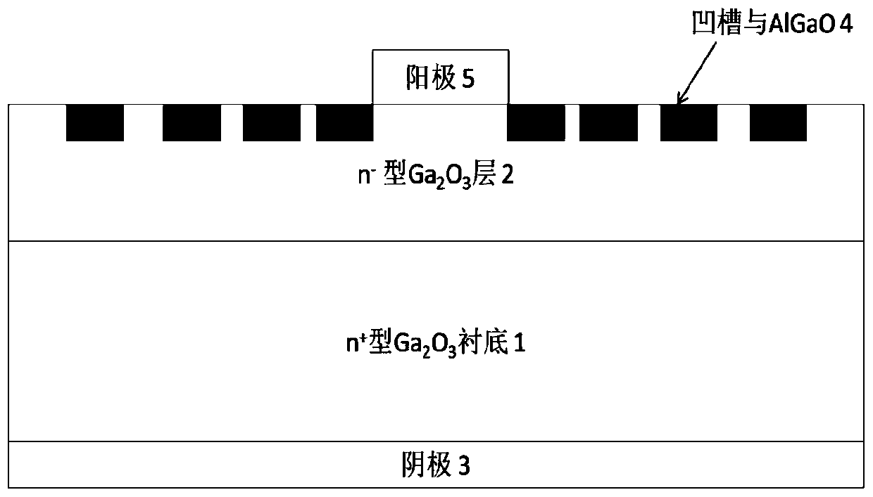
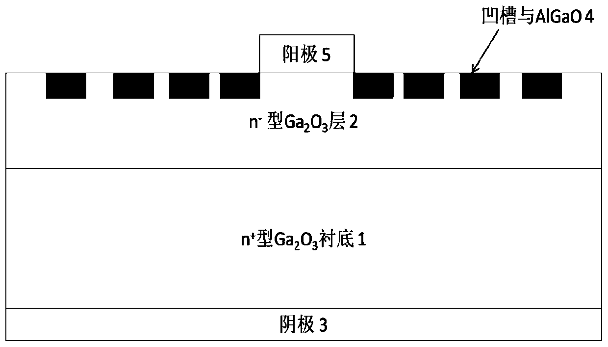
A Schottky diode and device structure technology, applied in the field of microelectronics, can solve the problems of increased parasitic effect and increased parasitic capacitance, and achieve the effects of stable physical and chemical properties, reduction of peak electric field, and perfect lattice structure
- Summary
- Abstract
- Description
- Claims
- Application Information
AI Technical Summary
Problems solved by technology
Method used
Image
Examples
Embodiment 1
[0030] Example 1, Schottky diodes with groove number M=4, groove depth of 30 nm, width of 2 μm, and groove pitches increasing by 0.3 μm were fabricated.
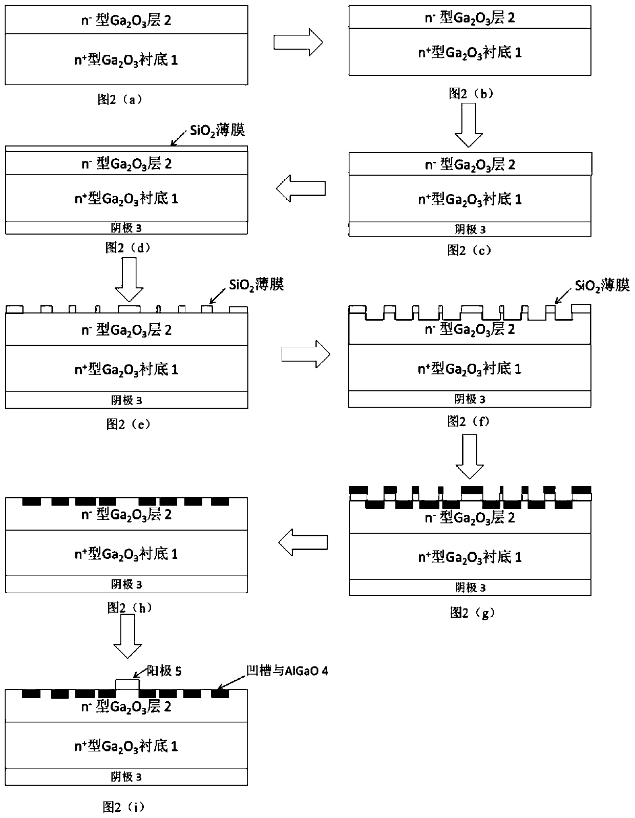
[0031] Step 1, cleaning, such as figure 2 (a).
[0032] Ga has been epitaxially grown on the substrate 2 o 3 The samples were cleaned organically under the conditions of ultrasonication of acetone solution for 5 minutes, ultrasonic solution of ethanol solution for 5 minutes, and then cleaned with deionized water, and then put into HF:H 2 Erosion was carried out in a solution of O=1:1 for 50s, and finally cleaned with flowing deionized water and dried with high-purity nitrogen.
[0033] Step 2, etch, such as figure 2 (b).
[0034] Put the cleaned sample face down into the ICP etching reaction chamber, and slightly etch the lower surface of the substrate. The process conditions are: the power of the upper electrode is 100W, the power of the lower electrode is 10W, the pressure of the reaction chamber is 30Pa, BCl 3 The...
Embodiment 2
[0049] Example 2, Schottky diodes with groove number M=5, groove depth of 40 nm, width of 2.5 μm, and groove pitches increasing by 0.4 μm were fabricated.
[0050] Step one, cleaning.
[0051] The specific implementation of this step is the same as step 1 of Embodiment 1.
[0052] Step two, etching.
[0053] The specific implementation of this step is the same as that of step 2 in Embodiment 1.
[0054] Step 3, preparing the cathode electrode.
[0055] The specific implementation of this step is the same as that of step 3 in Embodiment 1.
[0056] Step 4, deposit SiO 2 mask.
[0057] The specific implementation of this step is the same as step 4 of Embodiment 1.
[0058] Step five, remove the SiO in the groove etching area 2 mask.
[0059] The specific implementation of this step is the same as that of step 5 in Embodiment 1.
[0060] Step six, etching grooves.
[0061] Put the sample into the ICP etching reaction chamber, the upper electrode power is 100W, the lower...
Embodiment 3
[0068] Example 3, Schottky diodes with groove number M=6, groove depth of 50 nm, width of 3 μm, and groove pitches increasing by 0.5 μm were fabricated.
[0069] Step A, wash.
[0070] The specific implementation of this step is the same as step 1 of Embodiment 1.
[0071] Step B, etching.
[0072] The specific implementation of this step is the same as that of step 2 in Embodiment 1.
[0073] Step C, preparing a cathode electrode.
[0074] The specific implementation of this step is the same as that of step 3 in Embodiment 1.
[0075] Step D, depositing SiO 2 mask.
[0076] The specific implementation of this step is the same as step 4 of Embodiment 1.
[0077] Step E, removing the SiO in the groove etching area 2 mask.
[0078] The specific implementation of this step is the same as that of step 5 in Embodiment 1.
[0079] Step F, etching grooves.
[0080] Put the sample into the ICP etching reaction chamber, the upper electrode power is 100W, the lower electrode p...
PUM
 Abstract
Description
Claims
Application Information
 - R&D
- Intellectual Property
- Life Sciences
- Materials
- Tech Scout
- Unparalleled Data Quality
- Higher Quality Content
- 60% Fewer Hallucinations
Browse by: Latest US Patents, China's latest patents, Technical Efficacy Thesaurus, Application Domain, Technology Topic, Popular Technical Reports.
© 2025 PatSnap. All rights reserved.Legal|Privacy policy|Modern Slavery Act Transparency Statement|Sitemap|About US| Contact US: help@patsnap.com


