Kiln

A kiln and kiln wall technology, applied in the field of kilns, can solve the problems of more electric power consumption, large heat loss, low heat recovery rate, etc., and achieve the effects of high waste heat recovery rate, energy saving, and less heat storage.

Inactive Publication Date: 2017-06-27
STATE GRID FUJIAN DEHUA POWER SUPPLY
View PDF0 Cites 1 Cited by
  • Summary
  • Abstract
  • Description
  • Claims
  • Application Information

AI Technical Summary

Problems solved by technology

[0002] The kiln is widely used in the roasting production of ceramic products, abrasives and metallurgical industries. The structure is divided into a pre-tropical zone, a firing zone, and a cooling zone. There are fixed walls and vaults on both sides and the top, and the rails laid on the bottom run Kiln car, the kiln car is made of silicon carbide material, and the combustion equipment is installed on both sides of the middle part of the tunnel kiln, forming a fixed high-temperature zone - the firing zone, blowing cold air at the kiln tail of the kiln to cool the last section of the kiln The product is provided with a heat extraction fan and an external pipeline on the outside of the wall, and the cooled waste heat is drawn back to the preheating zone through the external pipeline by the exhaust fan for reuse. However, the existing kiln has the following disadvantages. One is In this method of waste heat utilization, since the pipes are arranged outside the furnace, part of the waste heat has lost heat in the process of passing through the pipes, and the heat that can be reused by the preheating zone is reduced, so the heat recovery rate is low and the heat loss is large. Outside the furnace, the noise is louder. Second, the kiln car is made of silicon carbide material, which has a strong heat absorption capacity, which makes the heat loss in the furnace greater, and requires more power consumption to ensure the normal production of the kiln.

Method used


Image

  • Kiln
  • Kiln

Examples


Embodiment Construction

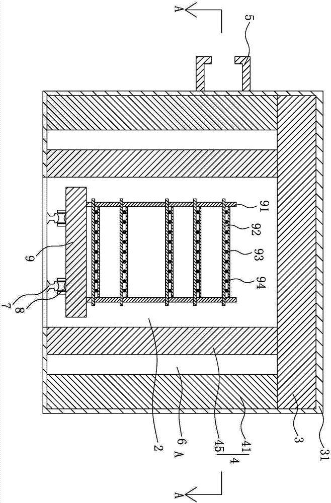
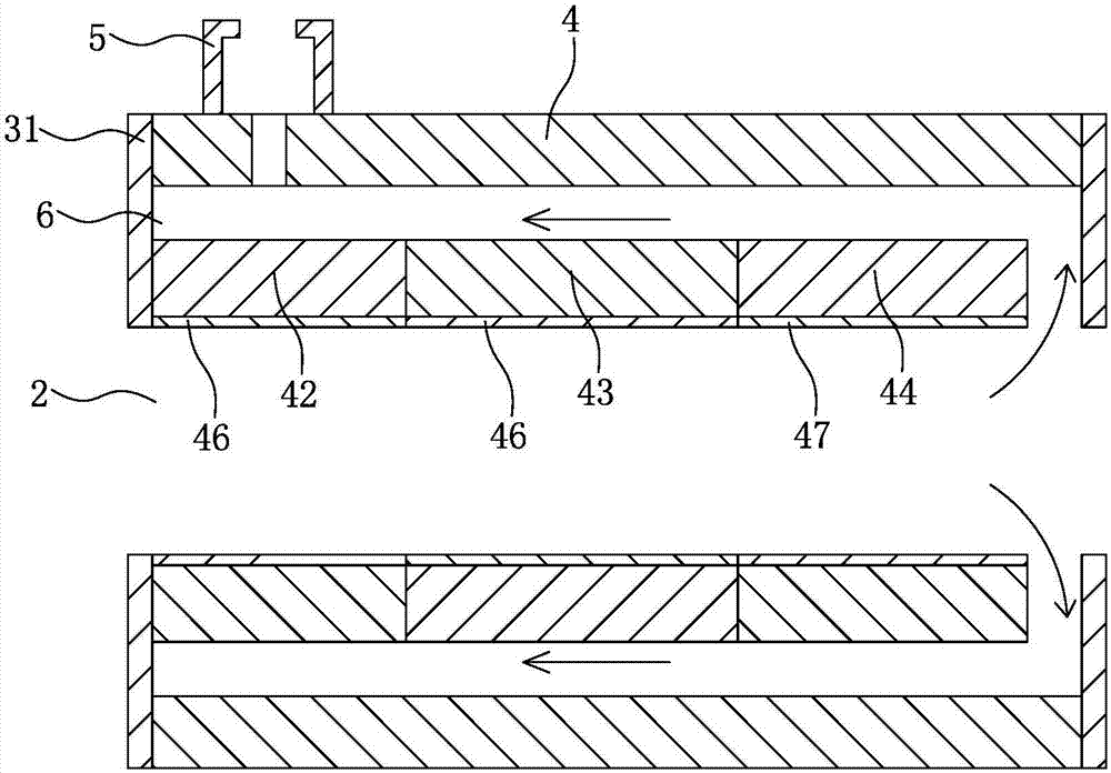
[0021] like figure 1 and figure 2 As shown, the kiln includes a kiln body and kiln furniture that can be moved in the kiln body for placing objects to be fired. The kiln body includes a furnace top 3 and side walls 4 that form a firing channel 2, and are arranged on the furnace top. 3 and the outer shell 31 of the side wall 4, the firing channel 2 includes a preheating zone, a firing zone and a cooling zone which are sequentially communicated from the inlet to the outlet, the side wall 4 on the inlet side of the preheating zone is provided with a chimney 5, The wall 4 is provided with a waste heat channel 6 extending in the direction of the firing channel 2. One end of the waste heat channel 6 is communicated with the cooling zone, and the other end is communicated with the chimney 5. The chimney has the function of drawing the waste heat of the cooling zone back to the preheating zone through the waste heat channel 6. The pumping force for reuse, the side wall 4 includes a ...


PUM


Abstract

The invention provides a kiln which comprises a kiln body and a kiln furniture, wherein the kiln furniture can move in the kiln body and is used for placing objects to be fired; the kiln body comprises a furnace top and a side wall, which form a firing channel; the firing channel comprises a preheating zone, a firing zone and a cooling zone, which are communicated in order; a chimney is arranged on the side wall on the entry side of the preheating zone, and a waste heat channel extending along the direction of the firing channel is formed in the side wall; one end of the waste heat channel is communicated with the cooling zone, and the other end of the waste heat channel is communicated with the chimney; the chimney has extracting force for extracting the waste heat of the cooling zone back to the preheating zone through the waste heat channel for recycling. The kiln has the advantages of high recycling rate of waste heat and small heat loss, reduces noises, reduces electric energy loss, and saves energy.

Description

technical field [0001] The present invention relates to a kiln. Background technique [0002] The kiln is widely used in the roasting production of ceramic products, abrasives and metallurgical industries. The kiln car is made of silicon carbide material. The combustion equipment is located on both sides of the middle of the tunnel kiln, forming a fixed high temperature zone - the firing zone. Cold air is blown into the kiln tail of the kiln to cool the latter section of the kiln. There are heat extraction fans and out-of-furnace pipes on the outside of the wall, and the cooled waste heat is drawn back to the preheating zone through the out-of-furnace pipes for reuse. However, the existing kilns have the following shortcomings: one is This method of waste heat utilization, because the pipeline is set outside the furnace, the waste heat has lost some heat in the process of passing through the pipeline, and the heat that can be reused in the preheating zone is reduced, so the...

Claims


Application Information

Patent Timeline
Patent Type & Authority Applications(China)
IPC IPC(8): F27B17/00F27D1/00F27D11/02F27D13/00F27D3/12F27D17/00
CPCF27B17/00F27D1/0006F27D3/123F27D11/02F27D13/00F27D17/004Y02P10/25
Inventor 陈琨黄金铭苏金辉陈为坤郑良伟林国仕
Owner STATE GRID FUJIAN DEHUA POWER SUPPLY
Why Eureka
Try Eureka