EMC-demand-requiring permanent magnet direct current motor of capacitor triangle-type connection structure

A technology of permanent magnet DC connection method, which is applied in the manufacture of motor generators, structural connections, electrical components, etc., can solve the problems of motor processing, high manufacturing cost, complicated processing technology, time-consuming and labor-intensive, etc., and achieve high electromagnetic compatibility Requirements, saving personnel, simple structure effect

Inactive Publication Date: 2017-06-27
深圳市利宏微形电机有限公司
View PDF5 Cites 2 Cited by
  • Summary
  • Abstract
  • Description
  • Claims
  • Application Information

AI Technical Summary

Problems solved by technology

The rotor assembly of the permanent magnet DC motor usually adopts 3 electrolytic capacitors to be placed in the gap of the 3-slot rotor coil, and one end of the capacitor pin is connected by a short-circuit copper ring to form a "Y" connection circuit, and a piezoresistor is welded. The absorbing effect of the capacitor element meets the requirements of the electromagnetic compatibility standard, and the following series of procedures and personnel are required: 2 people for capacitor cutting and shaping, 1 person for gap welding of the short-circuit ring, 3 people for installing the short-circuit ring on the capacitor, and 1 person for welding the short-circuit ring and the negative electrode of the capacitor , 2 people for installing the rotor on the short-circuit ring, positioning, 0.5 people for capacitance testing, and 0.5 people for cutting off the excess capacitor pins on the short-circuit ring. The processing technology is complex, cumbersome, time-consuming and labor-intensive, and the processing and manufacturing costs of the motor are high

Method used


Image

  • EMC-demand-requiring permanent magnet direct current motor of capacitor triangle-type connection structure
  • EMC-demand-requiring permanent magnet direct current motor of capacitor triangle-type connection structure
  • EMC-demand-requiring permanent magnet direct current motor of capacitor triangle-type connection structure

Examples


Embodiment 1

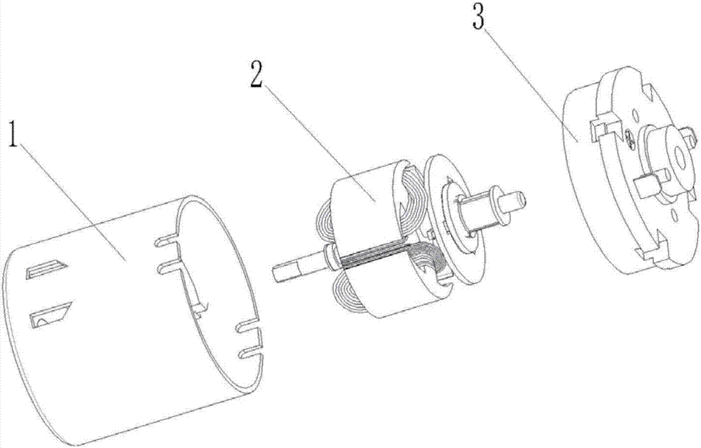
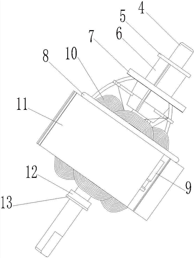
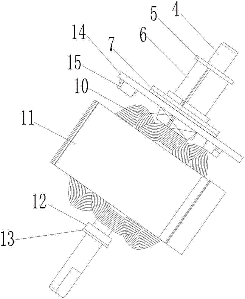
[0019] like figure 1 and image 3 As shown, the present invention provides a permanent magnet DC motor with a capacitor delta connection structure that meets EMC requirements, including a stator assembly 1, a rotor assembly 2 and a rear cover assembly 3, and the rotor assembly 2 is arranged in the stator assembly 1 , the end cover assembly 3 is arranged at one end of the stator assembly 1; the rotor assembly 2 includes a motor shaft 4, an oil baffle plate 5, a commutator 6, a piezoresistor 7, a PCB board 14, a rotor coil 10, an iron Core 11, copper sleeve 12 and gasket 13; the oil baffle plate 5, commutator 6, varistor 7, PCB board 14, iron core 11, copper sleeve 12 and gasket 13 are arranged on the motor shaft 4 in sequence , the rotor coil 10 is wound between the slots of the rotor core 11; the PCB board 14 is provided with three chip capacitors 15, and the chip capacitors 15 are connected to the commutator 6 through the PCB board 14; The two patch capacitors are connected...


PUM


Abstract

The invention discloses a permanent magnet direct current motor with a capacitor delta connection structure meeting EMC requirements, and belongs to the technical field of permanent magnet direct current motors. The rotor assembly of the permanent magnet DC motor includes the motor shaft and the oil baffle plate, commutator, varistor, PCB board, iron core, copper sleeve and gasket arranged on it in sequence. The rotor coil of the rotor assembly is wound on the rotor iron Between the core slots; the PCB board is provided with several chip capacitors, and the chip capacitors are connected to the commutator through the PCB board; the several chip capacitors are connected on the PCB board through a "△" type connection circuit , the piezoresistor is placed on the upper layer of the PCB and welded to the commutator pin. The permanent magnet DC motor of the present invention replaces the traditional structural design of placing electrolytic capacitors in the rotor coil gap by introducing a PCB board with patch capacitors, so as to achieve higher EMC effects and reduce processing and manufacturing costs.

Description

technical field [0001] The invention belongs to the technical field of permanent magnet direct current motors, in particular to a permanent magnet direct current motor with a capacitor delta connection structure meeting EMC requirements. Background technique [0002] The permanent magnet DC motor that meets the requirements of EMC (Electro Magnetic Compatibility, Electromagnetic Compatibility) means that the electromagnetic interference generated by the permanent magnet DC motor on the environment during normal operation cannot exceed a certain limit; to avoid the impact of electromagnetic waves on social production activities harm to human health. [0003] Since the permanent magnet DC motor needs to pass the EMC test, based on this consideration, in the prior art, capacitors are welded on the commutator segments to achieve the effect of passing the EMC test. [0004] A permanent magnet direct current motor meeting EMC requirements in the prior art includes a stator assemb...

Claims


Application Information

Patent Timeline
Patent Type & Authority Applications(China)
IPC IPC(8): H02K11/028H02K15/00
CPCH02K11/028H02K15/00H02K2211/03H02K2213/03
Inventor 黄美建冯武超李相银董浩
Owner 深圳市利宏微形电机有限公司
Why Eureka
Try Eureka