Plasma oxidation polishing system and method

A plasma and helium technology, applied in grinding/polishing equipment, grinding/polishing safety devices, manufacturing tools, etc., can solve problems such as difficulty in obtaining high-quality surfaces that meet optical application requirements

Pending Publication Date: 2017-07-07
ARMY ENG UNIV OF PLA
View PDF0 Cites 2 Cited by
  • Summary
  • Abstract
  • Description
  • Claims
  • Application Information

AI Technical Summary

Problems solved by technology

It can be seen from the sintering preparation process that RB-SiC contains two phases, SiC and Si. Due to the difference in physical and chemical properties between the SiC phase and the Si phase, it is difficult to directly process RB-SiC to obtain a high-quality surface that meets the requirements of optical applications.

Method used


Image

  • Plasma oxidation polishing system and method

Examples


Embodiment 1

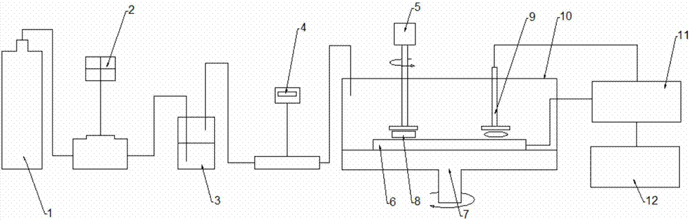
[0023] This embodiment provides a plasma oxidation polishing system, such as figure 1 As shown, the system includes a helium tank 1. The helium tank 1 is connected to a water bottle 3 through a gas pipe, and the water bottle 3 is connected to a polishing studio through a gas pipe. The polishing studio includes a horizontally arranged rotary table 7, and a polishing block 6 is arranged on the rotary table 7. A sample 8 is placed on the upper surface of the polishing block 6, a rotating motor 5 is fixedly connected above the sample 8, an electrode 9 is also connected to the upper surface of the rotary table 7, and the rotary table 7 and the electrode 9 are respectively connected to the manual matcher 11 through wires, and the manual matcher 11. Connect the radio frequency power supply 12.

[0024] A flow meter 2 is arranged between the aforementioned helium tank 1 and the water bottle 3 . A dew point meter 4 is installed between the aforementioned water receiving bottle 3 and t...


PUM


Abstract

The invention discloses a plasma oxidation polishing system. The plasma oxidation polishing system comprises a helium tank. The helium tank is connected with a water bottle through a gas pipe. The water bottle communicates with a polishing work chamber through a gas pipe. The polishing work chamber comprises a rotating platform which is horizontally arranged. The rotating platform is provided with a polishing block. A sample is placed on the upper surface of the polishing block. A rotating motor is fixedly connected above the sample. The upper surface of the rotating platform is further connected with an electrode. The rotating platform and the electrode are connected with a manual matcher through wires separately. The manual matcher is connected with a radio-frequency power supply. The invention further discloses a plasma oxidation polishing method. According to the plasma oxidation polishing system and method, the power of the radio-frequency power supply can be adjusted conveniently, and an oxidation airflow composition can be replaced easily; and meanwhile the characteristics that the water vapor content can be adjusted and the free radical concentration can be detected are achieved.

Description

technical field [0001] The invention belongs to oxidation polishing equipment, in particular to a plasma oxidation polishing system and method. Background technique [0002] The research on the application of silicon carbide (SiC) as an optical part began in the 1970s. Due to its high mechanical hardness, strong chemical stability, good thermal stability, high surface quality, high specific stiffness, small thermal deformation coefficient, and small thermal expansion coefficient , good dimensional stability, good optical machinability, good radiation resistance and other advantages, it has been widely used in the field of optics, especially in space optical systems, and its processing technology has become one of the research hotspots in the field of optical mirror processing. According to the preparation process, commonly used SiC materials can be divided into four types: hot press sintered SiC (HP-SiC), atmospheric pressure sintered SiC (S-SiC), reaction sintered SiC (RB-S...

Claims


Application Information

Patent Timeline
Patent Type & Authority Applications(China)
IPC IPC(8): B24B1/00B24B27/033B24B41/00B24B55/00
CPCB24B1/002B24B27/033B24B41/00B24B55/00
Inventor 沈新民涂群章何晓晖李治中唐建张晓南王新晴殷勤王东白攀峰
Owner ARMY ENG UNIV OF PLA
Why Eureka
Try Eureka