Optical transmit-receive module

A technology of optical transceiver components and optical signals, applied in optical components, light guides, optics, etc., can solve the problems of coupling efficiency drop, two optical paths cannot be aligned with coupling efficiency at the same time, and cannot be integrally formed, so as to simplify the structure and process, The effect of omitting the calibration action

Active Publication Date: 2017-07-14
HUAWEI TECH CO LTD
View PDF5 Cites 12 Cited by
  • Summary
  • Abstract
  • Description
  • Claims
  • Application Information

AI Technical Summary

Problems solved by technology

[0004] In the above optical transceiver assembly, since the first lens 931 and the second lens 922 are coaxially arranged, and the axis is perpendicular to the third lens 932, the three cannot be integrally formed on the same main body element 92, only the first lens 931 is arranged on the insertion element 93, and the assembly between the main body element 92 and the insertion element 93 inevitably causes the relative position tolerance between the first lens 931, the second lens 922, and the third lens 932 to deteriorate, which will cause coupling The two optical paths cannot be aligned at the same time or the coupling efficiency of one of them is low
In addition, due to the large coupling tolerance between the light output direction of the laser 96 (the Z-axis direction of the laser) and the light-incoming direction of the detector 95 (the Z-axis direction of the detector), the tolerances in other directions (X / Y axis) are relatively small The light-emitting direction of the prior art laser 96 and the light-incoming direction of the detector 95 are not in the same direction (the better Z-axis direction of the laser tolerance is affected by the poor X / Y-axis direction of the detector tolerance during coupling, causing the laser When 96 and detector 95 are coupled at the same time, the overall coupling tolerance changes, and there are defects such as decreased coupling efficiency and inability to align at the same time

Method used


Image

  • Optical transmit-receive module
  • Optical transmit-receive module
  • Optical transmit-receive module

Examples


Embodiment Construction

[0043] The embodiments of the present invention will be described below with reference to the accompanying drawings in the embodiments of the present invention.

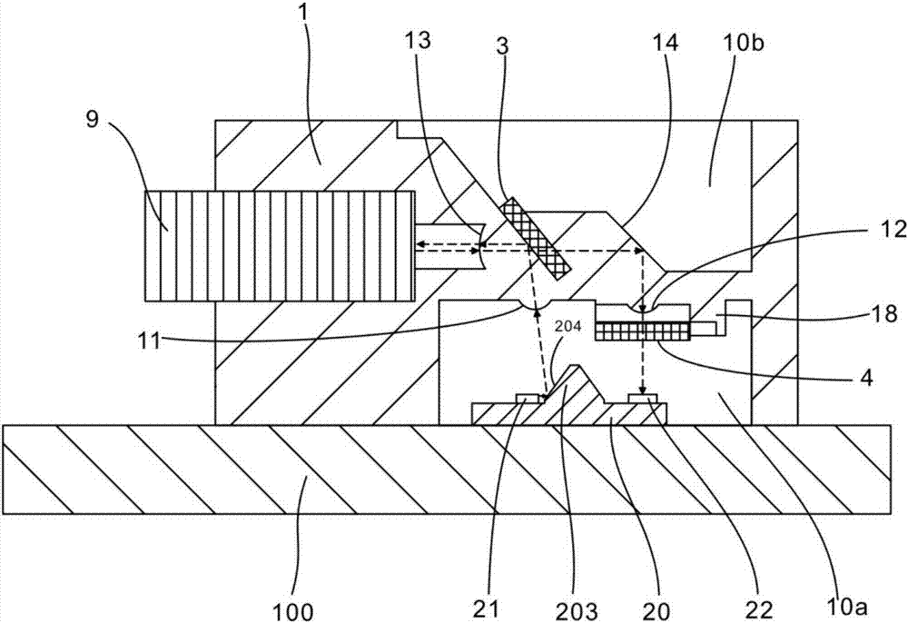
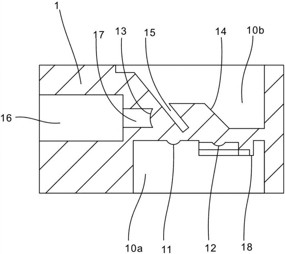
[0044] see figure 2 , is a schematic diagram of an optical transceiver component provided by the first embodiment of the present invention. It should be known that the optical transceiver component is used to convert electrical signals into optical signals (referred to as "electrical-optical conversion") and conduct them into optical fibers, and to conduct and convert optical signals transmitted in optical fibers into electrical signals (referred to as "photoelectric conversion"). ").

[0045] figure 2 The shown optical transceiver assembly includes a circuit board 100 , a light guide body 1 , a wavelength division multiplexing filter 3 , a first reflective surface 14 , a laser 21 and a detector 22 . The light guide body 1 is fixed on the circuit board 100. The light guide body 1 is integrally formed with a plur...


PUM


Abstract

The embodiment of the invention discloses an optical transmit-receive module. The module comprises a circuit board, an optical guide main body, a wavelength division multiplexing optical filter, a first reflection surface, a laser and a detector. The optical guide main body is fixed at the upper surface of the circuit board, the optical guide main body has a first cavity, the opening of the first cavity faces the circuit board, a transmission lens and a receiving lens are formed on the bottom wall of the first cavity, and the protruding direction of the protruding surface of the transmission lens and the protruding direction of the protruding surface of the receiving lens both face the circuit board. The optical transmit-receive module can facilitate the demoulding after the injection moulding of the transmission lens and the receiving lens at the optical guide main body to allow the two lenses to perform one-time moulding on the optical guide main body so as to omit the calibration motion between the two lenses, simplify the structure and the process of the optical transmit-receive module, eliminate the tolerance caused by secondary assembling and ensure the yield rate and production efficiency; and moreover, the protruding directions of the protruding surfaces of the transmission lens and the receiving lens are the same to allow the optical paths thereof to perform alignment at the same time so as to improve the coupling efficiency.

Description

technical field [0001] The invention relates to the terminal technology of optical fiber access, in particular to an optical transceiver component. Background technique [0002] The optical transceiver assembly (BO SA, bidirectional optical sub-assembly) is the core component of the access network terminal product (the cost accounts for more than 40%), and is used to realize the conversion function of optical signal and electrical signal. [0003] See figure 1 , the optical transceiver assembly in the prior art includes a circuit board 91, a main body element 92 attached to the circuit board 91 and an insertion element 93 plugged into the main body element 92; a carrier 94 and a detector 95 are arranged on the circuit board 91, The detector 95 is directly mounted and electrically connected to the circuit board 91 , a laser 96 is arranged on the carrier 94 , and the laser 96 is electrically connected to the circuit board 91 . The insertion element 93 is provided with a firs...

Claims


Application Information

Patent Timeline
Patent Type & Authority Applications(China)
IPC IPC(8): G02B6/42
CPCG02B6/4204G02B6/4214G02B6/4215G02B6/4246
Inventor 梁韬谢荣华孙敏
Owner HUAWEI TECH CO LTD
Why Eureka
Try Eureka