Integrated collaborative sulfur trioxide removal device suitable for high-sulphur coal and working method of integrated collaborative sulfur trioxide removal device

A sulfur trioxide and high-sulfur coal technology, applied in chemical instruments and methods, separation methods, gas treatment, etc., can solve problems such as weakened sulfur trioxide removal effect, alkali poisoning of SCR catalyst, and influence on dust specific resistance, etc., to achieve The effect of improving dust removal efficiency, good environmental protection, and solving corrosion problems

Pending Publication Date: 2017-07-21
HUADIAN ELECTRIC POWER SCI INST CO LTD
View PDF8 Cites 9 Cited by
  • Summary
  • Abstract
  • Description
  • Claims
  • Application Information

AI Technical Summary

Problems solved by technology

However, this method has a large amount of absorbent under the requirement of high sulfur trioxide removal efficiency, and excessive absorbent is likely to cause alkali poisoning of the SCR catalyst and affect the specific resistance of dust, etc.
[0009] Patents related to the present invention, such as CN104879764 A - "Deep Waste Heat Recovery and Cooperative Removal of Pollutants in Flue Gas Device and Method", aiming at the condition that the base sulfur content received by coal burning is less than 1.5%, it is achieved through pre-low temperature saving The coal burner lowers the flue gas temperature to 85-95°C to realize the condensation and removal of sulfur trioxide, and for the condition that the sulfur content is greater than 1.5%, the flue gas temperature at the outlet of the low-temperature economizer must be controlled above the acid dew point (105-115°C ) to avoid corrosion of the heat exchanger. Under this condition, the removal efficiency of sulfur trioxide will be limited. Even if a deep cooling is set at the outlet of the dust collector, the removal effect of sulfur trioxide will be significantly weakened due to the lack of high-concentration dust conditions.

Method used


Image

  • Integrated collaborative sulfur trioxide removal device suitable for high-sulphur coal and working method of integrated collaborative sulfur trioxide removal device

Examples


Embodiment Construction

[0019] The present invention will be further described in detail below in conjunction with the accompanying drawings and examples. The following examples are explanations of the present invention and the present invention is not limited to the following examples. In this embodiment, "rear" is equivalent to "along the direction of flue gas flow".

[0020] Example.

[0021] see figure 1 .

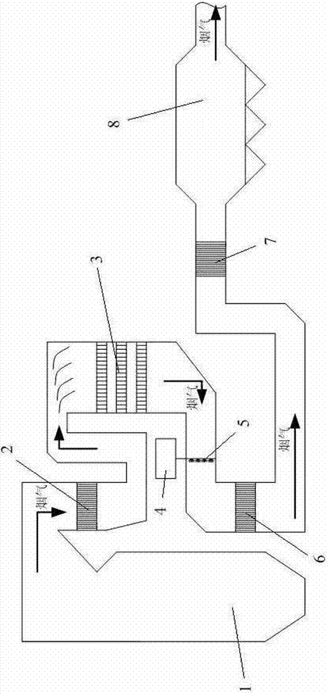
[0022] This embodiment is an integrated and coordinated sulfur trioxide removal device suitable for high-sulfur coal, including a boiler 1 and multiple flues.

[0023] The rear of the boiler 1 is provided with an economizer 2 , an SCR denitrification reactor 3 , an air preheater 6 , a low-temperature economizer 7 and an electrostatic precipitator 8 in sequence. The boiler 1 is connected to the economizer 2 through the flue, the economizer 2 is connected to the SCR denitrification reactor 3 through the flue, the SCR denitrification reactor 3 is connected to the air preheater 6 through the f...


PUM


Abstract

The invention relates to an integrated collaborative sulfur trioxide removal device suitable for high-sulphur coal. The integrated collaborative sulfur trioxide removal device comprises a boiler and a plurality of flues. The integrated collaborative sulfur trioxide removal device is characterized in that a coal economizer, an SCR (selective catalytic reduction) denitration reactor, an air pre-heater, a low-temperature coal economizer and a static dust remover are sequentially arranged in rear of the boiler; the boiler is connected with the coal economizer through the flue, the coal economizer is connected with the SCR denitration reactor through the flue, the SCR denitration reactor is connected with the air pre-heater through the flue, the air pre-heater is connected with the low-temperature coal economizer through the flue, and the low-temperature coal economizer is connected with the static dust remover through the flue; an alkaline absorbent spraying device is arranged in the flue between the SCR denitration reactor and the air pre-heater, and is connected with an alkaline absorbent storage device; a tail flue gas treatment device is arranged in rear of the static dust remover. The invention further relates to a working method of the device.

Description

technical field [0001] The invention belongs to the fields of industrial waste gas purification, environmental protection and energy, and in particular relates to an integrated and coordinated sulfur trioxide removal device suitable for high-sulfur coal and a working method thereof. Background technique [0002] my country's coal-based energy structure will not change for a long time. Therefore, controlling the emission of coal-fired flue gas pollutants is an important task for my country's air pollution control. In the current situation where conventional flue gas pollutants in coal-fired power plants require comprehensive ultra-low emissions, sulfur trioxide emissions have attracted more and more attention due to the lack of control methods and high hazards, especially the use of high-sulfur coal (burning The base sulfur content of the coal received is greater than 3%). Due to the combustion in the furnace and SCR denitrification, the unit will cause a large amount of sulf...

Claims


Application Information

Patent Timeline
Patent Type & Authority Applications(China)
IPC IPC(8): B01D53/50B01D53/83B01D53/73
CPCB01D53/002B01D53/504B01D53/73B01D2251/304B01D2251/402B01D2251/404B01D2251/604B01D2251/606B01D2258/0283B01D2259/128
Inventor 张杨朱跃裴煜坤江建平冯前伟
Owner HUADIAN ELECTRIC POWER SCI INST CO LTD
Why Eureka
Try Eureka