Excitation control method for electro-excitation long-afterglow light-emitting system

A long afterglow luminescence and electro-excitation technology, which is applied in the direction of light control, electroluminescence light source, non-electric variable control, etc., can solve the problems of low excitation efficiency, too simple function of the drive control circuit, and low minimum brightness value of the luminescence system, etc. problem, to achieve the effect of optimal design

Active Publication Date: 2017-07-21
ZHEJIANG MINGHUI LUMINESCENCE TECH CO LTD
View PDF8 Cites 4 Cited by
  • Summary
  • Abstract
  • Description
  • Claims
  • Application Information

AI Technical Summary

Problems solved by technology

[0006] 1. Single luminous effect
Existing excitation control methods generally only have one continuous power-on excitation period T in a cycle T ON , so the excitation control method is single; the function of the drive control circuit (2) is too simple to meet the special effect requirements of different application fields, so its application field has great limitations
[0007] For example, using the existing excitation control method, at the moment of power-on, due to the sudden increase of the current, the luminous intensity of the electroluminescent source (3) will suddenly increase and the luminous intensity of the entire electro-excitation long-afterglow luminescent system will suddenly increase. , resulting in a serious glare effect, great irritation and damage to the human eye, and poor luminous effect, so there are limitations in use in some occasions
[0008] For example, when the electro-excitation long-lasting light-emitting system needs to set a flashing reminder between the excitation intervals, the existing excitation control method has certain design difficulties in circuit control and will increase manufacturing costs.
[0009] 2. Under some specific conditions, the excitation efficiency of the electroluminescence system is low
Sometimes there is a waste of power consumption or the phenomenon that the minimum brightness value of the lighting system is low
[0010] For example, when the current amplitude is too low, the luminous intensity of the electroluminescent source (3) is not enough when it is energized, so that the e

Method used


Image

  • Excitation control method for electro-excitation long-afterglow light-emitting system
  • Excitation control method for electro-excitation long-afterglow light-emitting system
  • Excitation control method for electro-excitation long-afterglow light-emitting system

Examples


Embodiment 1

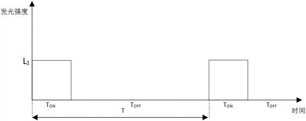
[0081] An electroluminescence long afterglow luminescence system adopts a traditional excitation method, and an electroluminescence source (3) emits light intermittently with a period of 10s and a duty ratio of 20%. The current passing through the electroluminescence source (3) in the Ton phase is a continuous constant current with an amplitude of 10 mA. Under this excitation control method, the luminous intensities of the electroluminescent source (3) and the long-lasting luminescent material (4) of the electro-excitation long-lasting luminescent system are as follows: Figure 8 , 10 As shown, the superimposed schematic diagram of the luminous intensity of the electro-excited long afterglow luminescent system is shown in Figure 12 shown.

[0082] Because the current amplitude of the electroluminescent source (3) is too small, the excitation efficiency of the long-lasting luminescent material (4) is too low. The excitation control method of the present invention is now used...

Embodiment 2

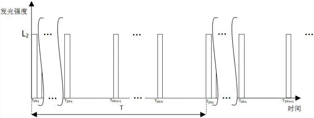
[0084] An electroluminescence long afterglow luminescence system adopts an improper excitation control method of the present invention, and the electroluminescence source (3) emits light intermittently with a period of 10s and a duty ratio of 6%. The current passing through the high-frequency excitation period of one cycle is a rectangular pulse current with an amplitude of 75mA, a frequency of 100HZ, and a pulse width of 2ms. Under this excitation control method, the luminous intensities of the electroluminescent source (3) and the long-lasting luminescent material (4) of the electro-excitation long-lasting luminescent system are as follows: Figure 15 , 17 As shown, the superimposed schematic diagram of the luminous intensity of the electro-excited long afterglow luminescent system is shown in Figure 19 As shown, the luminous intensity change of the electro-excited long-lasting light-emitting system observed by the human eye, that is, the average luminous intensity of the ...

Embodiment 3

[0087]An electro-excited long afterglow luminescent system, comprising a power supply (1), a drive control circuit (2), an LED light source (3), and a long afterglow luminescent material (4); the power supply (1) is a storage battery; the The drive control circuit (2) includes a drive circuit and a PWM control circuit; the PWM control circuit is a single-chip microcomputer with a PWM control function, connected to the loop through a MOS tube, and controlled by outputting a PWM signal to control the on-off of the MOS tube Excitation of the LED light emitting source (3); the LED light emitting source (3) is arranged on the bottom surface or below the long afterglow luminescent material (4), and plays the role of actively emitting light and exciting the long afterglow luminescent material (4); the LED The light emitting source (3) and the power supply (1) are respectively connected with the drive circuit through lines to form a closed loop.

[0088] After the circuit is turned on...


PUM


Abstract

The invention discloses an excitation control method for an electro-excitation long-afterglow light-emitting system. A drive control circuit (2) controls an electroluminescence light source (3) to be turned on and emit light in a certain period T and at a duty ratio T0N/T, and excites a long-afterglow light-emitting material (4). There is N discontinuous power-on excitation time segments TON1, TON2,...,TON N in one period, wherein N is greater than or equal to two, and TON is the sum of the TON1, TON2,...,TON N. The method achieves the adjustment of the power-on light intensity of the electroluminescence light source (3) through the changing of a drive current, and enables the light intensity to be within the higher-excitation-power section of the long-afterglow light-emitting material (4). A PWM circuit is used for controlling a mode adjustment period or the duty ratio, thereby controlling the power consumption of the electroluminescence light source (3). The method can reduce the power consumption under the condition that the lowest brightness is not changed, or increase the excitation power of the long-afterglow light-emitting material (4) under the condition that the power consumption is not increased, thereby improving the brightness. Moreover, the method can achieve the design according to the needs, so as to meet various types of needs.

Description

technical field [0001] The invention relates to the application field of light emitting devices, in particular to an excitation control method of an electro-excitation long afterglow light emitting system with energy-saving light emitting function. [0002] technical background [0003] The electro-excited long afterglow luminescence system is a new type of luminescence system developed in recent years. The structural principle diagram of this electro-excited long afterglow luminescence system is shown in figure 1 As shown, it generally includes a power supply (1), a drive control circuit (2), an electroluminescence source (3) and a long-lasting luminescent material (4), a power supply (1), a drive control circuit (2), an electroluminescence source ( 3) Connected by lines, its working principle is to drive the control circuit (2) to control the power supply (1) according to a certain period T and duty cycle T ON / T supplies power to the electroluminescent source (3), so tha...

Claims


Application Information

Patent Timeline
IPC IPC(8): G05D25/02H05B44/00
CPCG05D25/02H05B45/00H05B44/00
Inventor 方显峰
Owner ZHEJIANG MINGHUI LUMINESCENCE TECH CO LTD
Why Eureka
Try Eureka