Vehicular radar array antenna

An array antenna and vehicle-mounted radar technology, which is applied to antennas, antenna arrays, antenna components, etc., can solve the problems of difficult design and debugging of 24G anti-collision radar antenna arrays, few mature cases for reference, and unfavorable application promotion. Improved radiation directivity, easy integration, narrow E-plane radiation beam angle

Active Publication Date: 2017-07-21
HUIZHOU SPEED WIRELESS TECH CO LTD
View PDF9 Cites 25 Cited by
  • Summary
  • Abstract
  • Description
  • Claims
  • Application Information

AI Technical Summary

Problems solved by technology

The design and debugging of 24G anti-collision radar antenna array are relatively difficult, and there are few mature cases in China for reference
At present, to meet the above technical requirements, the corresponding structure will become complicated and the cost will increase, which is not conducive to application and promotion

Method used


Image

  • Vehicular radar array antenna
  • Vehicular radar array antenna
  • Vehicular radar array antenna

Examples


Embodiment Construction

[0027] In order to facilitate the understanding of those skilled in the art, the present invention will be further described in detail below with reference to the drawings and embodiments.

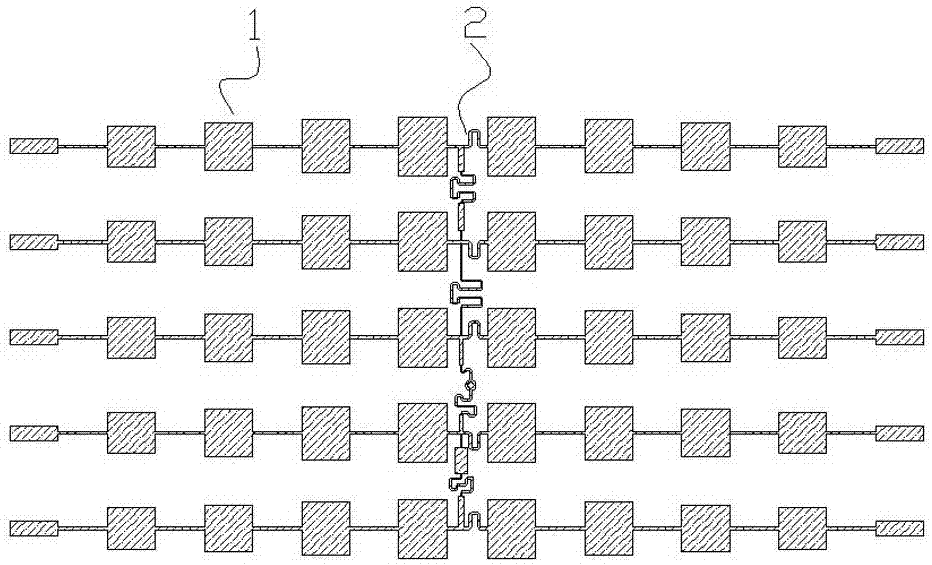
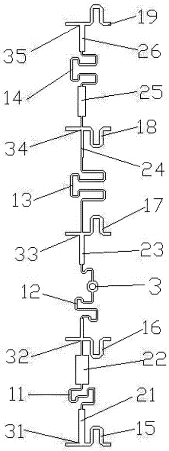
[0028] This embodiment discloses a 24G vehicle-mounted anti-collision radar array antenna, such as figure 1 As shown, it can be used as the transmitting end or receiving end of the 24G vehicle-mounted anti-collision radar antenna. This embodiment takes the transmitting end as an example, and proposes a new type of 24G / 77G impedance matching network design. The impedance applied to the antenna array at the transmitting end The matching form is researched based on the relevant theory of microwave / millimeter wave impedance matching. The array antenna includes a radiation array 1 composed of 5×10 radiation arrays, the radiation array 1 is the radiation part, and an impedance matching network 2 is set on the same plane of the radiation array 1, and the radiation array uses the impedance matchin...


PUM


Abstract

The invention provides a vehicular radar array antenna. The vehicular radar array antenna comprises a radiation fin array and an impedance matching network arranged on the same plane, and the radiation fin array is configured in a bilateral symmetry manner by taking the impedance matching network as the center axis. According to the invention, a novel feed network is employed, based on the microstrip line impedance match and phase shift principle, relevant parameter demands of the antenna radiation array are achieved by means of a simple implementation form, and furthermore product optimization is achieved. The simulation of the vehicular anticollision radar array antenna and the debugging of the antenna sample are convenient and fast, by arranging the impedance matching network and the array antenna in the same plane, the whole radar antenna profile is reduced, and the duty ratio of the antenna feed part in the whole vehicular radar is effectively reduced. By employing the novel design concept and design method, a conventional feed power splitting network structure with a complicated back side is broken through, electromagnetic interference on other radio frequency devices is effectively reduced, and the vehicular radar array antenna has a deep business application value in the actual engineering.

Description

technical field [0001] The present invention relates to the field of antennas, and more specifically, to a vehicle-mounted radar array antenna. Background technique [0002] A driverless car is a smart car that senses the road environment through an on-board sensor system, automatically plans a driving route, and controls the vehicle to reach a predetermined target. It uses on-board sensors to perceive the surrounding environment of the vehicle, and controls the steering and speed of the vehicle based on the road, vehicle position and obstacle information obtained from the perception, so that the vehicle can drive safely and reliably on the road. Integrating many technologies such as automatic control, architecture, artificial intelligence, and visual computing, it is a product of the highly developed computer science, pattern recognition, and intelligent control technologies. It is also an important symbol to measure a country's scientific research strength and industrial l...

Claims


Application Information

Patent Timeline
Patent Type & Authority Applications(China)
IPC IPC(8): H01Q1/38H01Q1/50H01Q21/00H01Q21/06H01Q1/32
CPCH01Q1/3233H01Q1/38H01Q1/50H01Q21/0075H01Q21/065
Inventor 张宏图李建法
Owner HUIZHOU SPEED WIRELESS TECH CO LTD
Why Eureka
Try Eureka