
Comprehensive utilization system for ring cooling machine waste gas and sintering large flue exhaust gas waste heat

The technology of flue gas waste heat and ring cooler is applied in the field of comprehensive utilization system of sintering waste heat, which can solve the problems of large investment and many equipment, and achieve the effect of reducing investment cost, reducing the number of equipment and improving power generation efficiency.

Pending Publication Date: 2017-08-11
HUATIAN NANJING ENG & TECH CORP MCC
View PDF5 Cites 0 Cited by
  • Summary
  • Abstract
  • Description
  • Claims
  • Application Information

AI Technical Summary

Problems solved by technology

At present, most domestic iron and steel plants only recycle the 250-450°C medium-temperature waste gas from the first and second stages of the ring cooler for the sintering cooling waste gas on the ring cooler, and do not recycle the 100-150°C low-temperature waste gas from the third stage. Only a small number of iron and steel plants recover the waste heat of high-temperature flue gas sintered by sintering machines, and the waste heat recovery of sintering cooling on the ring cooler and the waste heat of high-temperature waste flue gas sintered by sintering machines are two independent recovery systems. There are many equipments and investment Big

Method used


Image

  • Comprehensive utilization system for ring cooling machine waste gas and sintering large flue exhaust gas waste heat

Examples


Embodiment 1

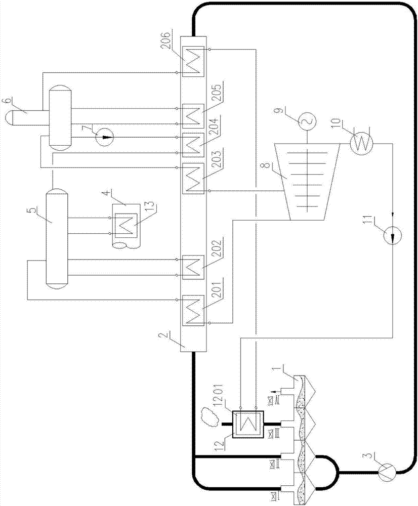
[0027] like figure 1 As shown, the waste heat recovered in this embodiment includes two parts: the waste heat of the high-temperature flue gas sintered by the sintering machine (in the large sintering flue) and the waste heat of the waste gas after cooling the sinter on the ring cooler. The waste heat boiler unit 2 recovers the waste heat of exhaust gas in zone I and zone II of the annular cooler 1, the low-temperature waste heat unit 12 recovers the waste heat of exhaust gas in zone III of the circular cooler, and the sintering large flue evaporator 13 recovers the high-temperature flue gas sintered by the sintering machine waste heat.

[0028] This embodiment is divided into two parts, one part is the flue gas system, and the other part is the steam-water power generation system.

[0029] Smoke and air system: the high-temperature exhaust gas discharged from the zone Ⅰ and zone Ⅱ on the ring cooler 1 is connected through the pipeline and merged. After the confluence, the te...


PUM


Abstract

The invention discloses a comprehensive utilization system for ring cooling machine waste gas and sintering large flue exhaust gas waste heat. The system comprises a ring cooling machine front area waste heat recycling device, a low pressure steam drum and a high pressure steam drum. The ring cooling machine front area waste recycling device comprises a heat exchange device. The heat exchange device comprises a box body, and a high pressure superheater, a high pressure evaporator, a low pressure superheater, a high pressure coal economizer, a low pressure evaporator and a low pressure coal economizer which are sequentially arranged in the box body in the exhaust gas flowing direction. High-temperature exhaust gas waste heat in a sintering large flue and sintering ore cooled waste gas waste heat of a ring cooling machine are recycled, low-temperature waste gas waste heat of the III area of the ring cooling machine is utilized, the system is reasonably arranged in the heated face of the sintering large flue and the ring cooling machine waste heat recycling device according to the second law of thermodynamics, flue gas waste heat in the flue is recycled stepwise, two kinds of high-grade steam are produced, the power generation efficiency is improved, one steam drum is adopted for recycling waste heat in the sintering large flue and the ring cooling machine, the equipment number is reduced, and the investment cost is reduced.

Description

technical field [0001] The invention relates to a system for comprehensive utilization of sintering waste heat. Background technique [0002] The waste heat resources in the sintering production process mainly include two parts: the waste heat of high-temperature waste flue gas from sintering machine and the waste heat of sinter cooling waste gas on the ring cooler. In the total energy consumption of the sintering process, the waste heat of these two parts of waste gas is close to 50%. heat. At present, sintering waste heat recovery is mainly used for power generation to meet the electricity demand of iron and steel process or to generate electricity on the grid to reduce the operating cost of iron and steel plants. At present, most domestic iron and steel plants only recycle the 250-450°C medium-temperature waste gas from the first and second stages of the ring cooler for the sintering cooling waste gas on the ring cooler, and do not recycle the 100-150°C low-temperature w...

Claims


Application Information

Patent Timeline
IPC IPC(8): F22B1/16F22D1/50F27D17/00
CPCF22B1/16F22D1/50F27D17/004Y02P10/25
Inventor 王雷
Owner HUATIAN NANJING ENG & TECH CORP MCC
Learn More