
Edge sensor system for active reflection plane of radio telescope, and detection method for active reflection plane edge sensor system

A radio telescope and sensor technology, which is applied to instruments, measuring devices, optical devices, etc., can solve the problem of low precision and seeing, heavy workload of batch real-time detection, and inability to real-time detection by radio telescopes and ensure the surface shape accuracy. And other issues

Inactive Publication Date: 2017-08-11
NANJING INST OF ASTRONOMICAL OPTICS & TECH NAT ASTRONOMICAL OBSE
View PDF4 Cites 10 Cited by
  • Summary
  • Abstract
  • Description
  • Claims
  • Application Information

AI Technical Summary

Problems solved by technology

Among them, methods such as theodolites, laser trackers, total stations, and laser rangefinders all have the ability to detect and guide the adjustment of the panel when the telescope is fixed in a certain attitude (such as the panel facing the sky or vertically facing the horizontal), so that The panel reaches the design tolerance index, which is mainly used for the overall panel shape detection and calibration after the panel is installed and before it is put into use. The disadvantage is that it is cumbersome, batch testing requires a large number of auxiliary targets and retroreflectors, and is not real-time; radio holography uses synchronous satellites , astronomical or artificial radio sources to measure the wavefront of the entire antenna, you only need to use the receiver of the telescope itself. The accuracy of this method can only reach 0.1 mm, and the imaging detection method in the visible light band cannot be applied here because of the relatively low precision of the antenna panel in the radio band and the problem of seeing.
[0006] The common disadvantage of the above radio telescope reflective surface detection methods is that it is only suitable for the detection and review of reflective surfaces at a single or certain height positions, and it is impossible to detect and ensure that the calibrated surface after the installation and adjustment of the radio telescope is real-time during the working process of the radio telescope. shape accuracy, the workload of batch real-time detection is particularly heavy
These shortcomings have become a big bottleneck in the process of radio telescope construction and operation and maintenance

Method used


Image

  • Edge sensor system for active reflection plane of radio telescope, and detection method for active reflection plane edge sensor system
  • Edge sensor system for active reflection plane of radio telescope, and detection method for active reflection plane edge sensor system
  • Edge sensor system for active reflection plane of radio telescope, and detection method for active reflection plane edge sensor system

Examples


Embodiment 1

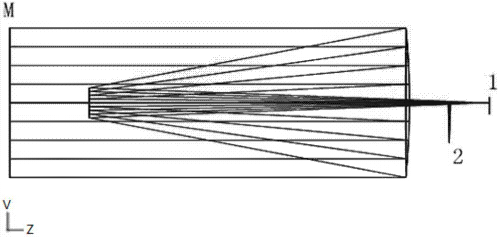
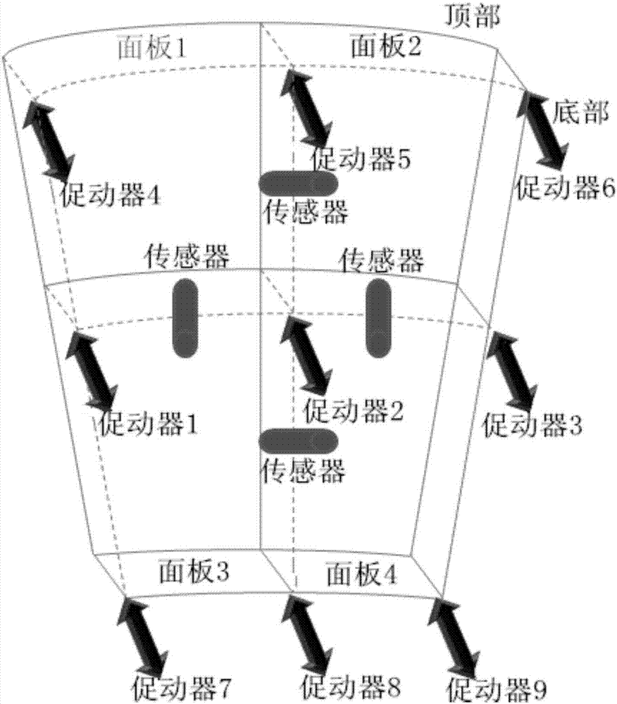
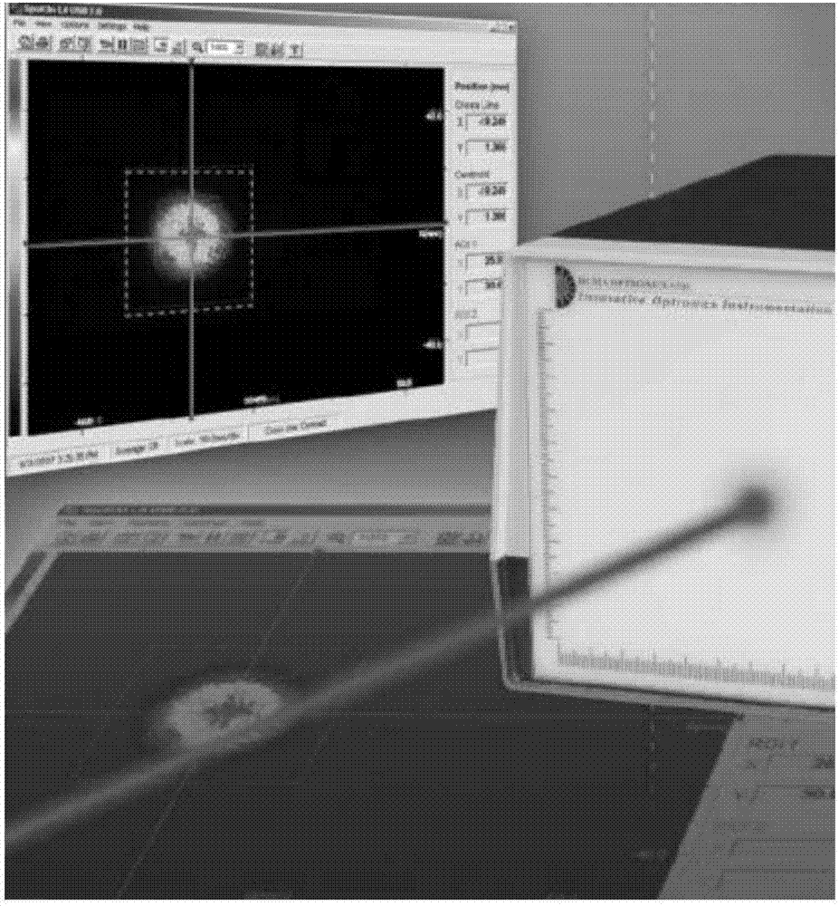
[0046] Embodiment 1, the edge displacement sensor of the reflector of the radio astronomy telescope, carries out figure 1 The optical design of the edge sensor in the center adopts a card system, which increases the focal length by turning the optical path, and the double reflection design eliminates chromatic aberration; the transmitting end (point light source) 2 and the receiving end (target surface) 1 share the optical path and are placed on the edge of a panel. The plane reflector M is placed on the other panel, and the two panels are connected by parallel light to form a complete edge sensor system; the collimated parallel light emitted by the sensor emitter (point light source) is reflected by the plane on the other panel The mirror is reflected back and received by the receiving end (target surface), and the image points are recorded (refer to image 3 The change of the position of the spot profile); through image processing (refer to Pic 4-1 , Figure 4-2 ) to obta...

Embodiment 2

[0047] Embodiment 2 is basically the same as Embodiment 1. In order to switch radio telescopes to different working modes or to achieve large-scale high-precision measurement, the receiver part (target surface) of the edge sensor in the above step (2) uses a high-precision electromagnet Control and switch the field of view / range or the measurement range control mechanism with sensors, realize the switching of two high-precision small measurement ranges, perform measurements in different ranges, and complete the real-time closed-loop calibration of the entire radio telescope.


PUM


Abstract

The invention discloses an edge sensor system for the active reflection plane of a radio telescope, and a detection method for the active reflection plane edge sensor system. The system is disposed on an active reflection panel of the radio telescope, and consists of an edge sensor, a plane reflector, a transmitting end and a receiving end for detecting light, and an image processing computer. Each two adjacent sub-panels in the whole active reflection panel serves as one group, and the edge sensor is disposed at the edge of the back surface of one sub-panel, and the plane reflector is disposed on the other sub-panel of the same group. A transmitting end point on the edge sensor transmits detection light. Two sub-panels are connected through detection light. The detection light is reflected by the plane reflector and is received by the receiving end, and then is transmitted to the image processing computer. The output end of the computer is connected with each displacement actuator. The edge sensor is designed for the active reflection panel of the radio telescope, achieves the real-time detection of a surface shape in an observation process, and achieves the real-time jointing detection and adjustment of batch panels.

Description

technical field [0001] The invention relates to an edge sensor optical detection system for the splicing detection of active reflective surfaces of radio telescopes based on the principle of optical reflection and image processing technology, which is very suitable for the splicing detection of active reflective panels of large-diameter radio telescopes and millimeter / submillimeter wave telescopes. In this way, the active correction of the active reflective surface is realized by combining the displacement actuator and other actuators. The invention also relates to the design of the active reflection surface edge sensor optical detection system and the common phase detection method. [0002] This invention is a key support project of the National Joint Fund, "Key Technology Research on the Active Surface of Large Radio Telescope", and the approval number is: U1331204. Background technique [0003] A radio telescope usually has a large aperture, and its antenna (main panel) ...

Claims


Application Information

Patent Timeline
Patent Type & Authority Applications(China)
IPC IPC(8): G01B11/24
CPCG01B11/24
Inventor 李国平李烨平张勇
Owner NANJING INST OF ASTRONOMICAL OPTICS & TECH NAT ASTRONOMICAL OBSE
Learn More