Latex paint wastewater treatment system and method

A wastewater treatment system, latex paint technology, applied in waste paint treatment, multi-stage water treatment, water/sewage treatment, etc., to prevent polarization or scaling, reduce power loss, adjust spacing and facilitate electrode plate replacement

Active Publication Date: 2017-08-18
SHAANXI RES DESIGN INST OF PETROLEUM CHEM IND
View PDF3 Cites 0 Cited by
  • Summary
  • Abstract
  • Description
  • Claims
  • Application Information

AI Technical Summary

Problems solved by technology

[0004] The technical problem to be solved by the present invention is to overcome the problems existing in the above-mentioned existing latex paint wastewater treatment process, to provide a method that can effectively break the emulsion, remove COD, suspended solids and refractory substances in sewage, improve biodegradability and undergo biochemical treatment. Emulsion paint wastewater treatment system and method meeting discharge or reuse standards

Method used


Image

  • Latex paint wastewater treatment system and method
  • Latex paint wastewater treatment system and method
  • Latex paint wastewater treatment system and method

Examples


Embodiment 2

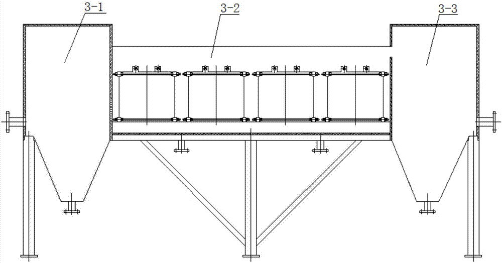
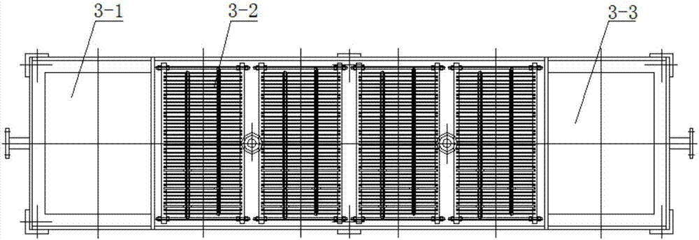
[0047] In this embodiment, the lower part of the side wall at the junction of the primary sedimentation tank 3-1 and the electrocoagulation reactor 3-2 is processed with evenly distributed water distribution holes, and the aperture of the water distribution holes is 10mm; the electrocoagulation reactor 3-2 is composed of The rectifier 3-2-1, the double-circuit cycle time relay 3-2-2, and the electrode group 3-2-3 are connected, and the number of the electrode group 3-2-3 is 1 group; two front insulating skeletons 3-2- The inner side of 3-7 is processed with 20 L-shaped slots at equal intervals along the length direction, and 20 straight slots are processed at equal intervals along the length direction on the rear insulating frame 3-2-3-1; the first rectangular electrode plate 3 - The distance between 2-3-2 and the second rectangular electrode plate 3-2-3-4 is 10 mm, the first rectangular electrode plate 3-2-3-2 and the second rectangular electrode plate 3-2-3- 4 The thickness is...

Embodiment 3

[0049] In this embodiment, the lower part of the side wall at the junction of the primary sedimentation tank 3-1 and the electrocoagulation reactor 3-2 is processed with evenly distributed water distribution holes, and the aperture of the water distribution holes is 30 mm; the electrocoagulation reactor 3-2 is composed of The rectifier 3-2-1, the double-circuit cycle time relay 3-2-2, and the electrode group 3-2-3 are connected, and the number of electrode groups 3-2-3 is 5 groups; two front insulating frames 3-2- The inner side of 3-7 is processed with 30 L-shaped slots at equal intervals along the length direction, and 30 straight slots are processed at equal intervals along the length direction on the rear insulating frame 3-2-3-1; the first rectangular electrode plate 3 - The distance between 2-3-2 and the second rectangular electrode plate 3-2-3-4 is 30 mm, the first rectangular electrode plate 3-2-3-2 and the second rectangular electrode plate 3-2-3- 4 The thickness is 6...


PUM

PropertyMeasurementUnit
thicknessaaaaaaaaaa
thicknessaaaaaaaaaa

Abstract

The invention discloses a system and a method for latex paint wastewater treatment. The wastewater treatment system comprises a constructed grid well, a sand settling basin, an open type electronic flocculator, an IC anaerobic reactor, an A/O2 biochemical reactor, a sloped tube settling basin, a sludge basin, a filter press, a ferro-manganese filter, a vertical electronic flocculator, a lift pump and a settling separation basin which are connected. In use, latex paint wastewater flows through the constructed grid well to remove granular impurities, then flows into the sand settling basin to remove granular filler, then flows into the open type electronic flocculator for emulsion breaking, layering and settlement, and then flows into the A/O2 biochemical reactor for biochemical treatment; the biochemical effluent water flows through the sloped tube settling basin for removing sludge; the obtained clear water flows into the vertical electronic flocculator for further electronic flocculation treatment; and the effluent water is filtered and then reused or discharged. The system and the method disclosed by the invention can effectively break emulsion, and remove COD, suspended matters and non-degradable substances in wastewater, and improves biodegradability; and the biochemically treated wastewater reaches discharge or reuse standards. The system and the method have the advantages of high treatment efficiency, and stable effluent.

Description

technical field [0001] The invention belongs to the technical field of sewage treatment, and in particular relates to a latex paint wastewater treatment system and method. Background technique [0002] In recent years, the amount of latex paint has been increasing year by year. Therefore, latex companies of various sizes are blooming all over the country. Due to the backwardness of the production process and the weak awareness of environmental protection, the treatment of latex paint production wastewater has not received due attention. [0003] Latex paint wastewater is mainly produced when washing production equipment, paint mixing tanks, paint buckets, pipelines and floors, and mainly contains chemical substances such as emulsions, emulsifiers, additives, colorants, pigments and fillers. In the production process of latex paint, the amount of wastewater is small but discharged intermittently, and the impact load is high; the COD concentration of latex paint wastewater is...

Claims


Application Information

Patent Timeline
Patent Type & Authority Applications(China)
IPC IPC(8): C02F9/14C02F103/14
CPCC02F9/00C02F2001/007C02F2103/14C02F3/28C02F3/30C02F2303/04C02F2301/08C02F2201/46105C02F2209/08C02F2209/10C02F2209/06C02F1/001C02F1/463C02F1/467Y02W10/10
Inventor 张国辉杨鸿鹰王丽莉王玲燕任蕊张玉娟
Owner SHAANXI RES DESIGN INST OF PETROLEUM CHEM IND
Why Eureka
Try Eureka