Copper alloy target

A copper alloy target and metal material technology, applied in metal material coating process, vacuum evaporation plating, coating and other directions, can solve the problems of difficult target utilization, poor operability, productivity and safety, and achieve low price, Effects of reduced abnormal discharge and excellent solder wettability

Active Publication Date: 2019-08-20
SUMITOMO METAL MINING CO LTD
View PDF13 Cites 2 Cited by
  • Summary
  • Abstract
  • Description
  • Claims
  • Application Information

AI Technical Summary

Problems solved by technology

Although it is considered to cut directly from the ingot in the shape of the final product by wire electric discharge machining, it is difficult to directly use it as a target due to the large number of holes in the ingot
In addition, although vacuum melting and vacuum casting are considered to remove voids inside the ingot, under vacuum conditions, silver is vapor-deposited on the inner wall of the melting furnace cavity, inspection window, oscillation coil, electrode terminals, etc. Partly, therefore, there is a problem that operability, productivity, and safety are significantly deteriorated

Method used


Image

  • Copper alloy target
  • Copper alloy target
  • Copper alloy target

Examples


Embodiment

[0046] Hereinafter, the present invention will be described in more detail using examples and comparative examples, but the present invention is not limited to the following examples at all.

[0047] "Examples and Comparative Examples"

manufacture example 1

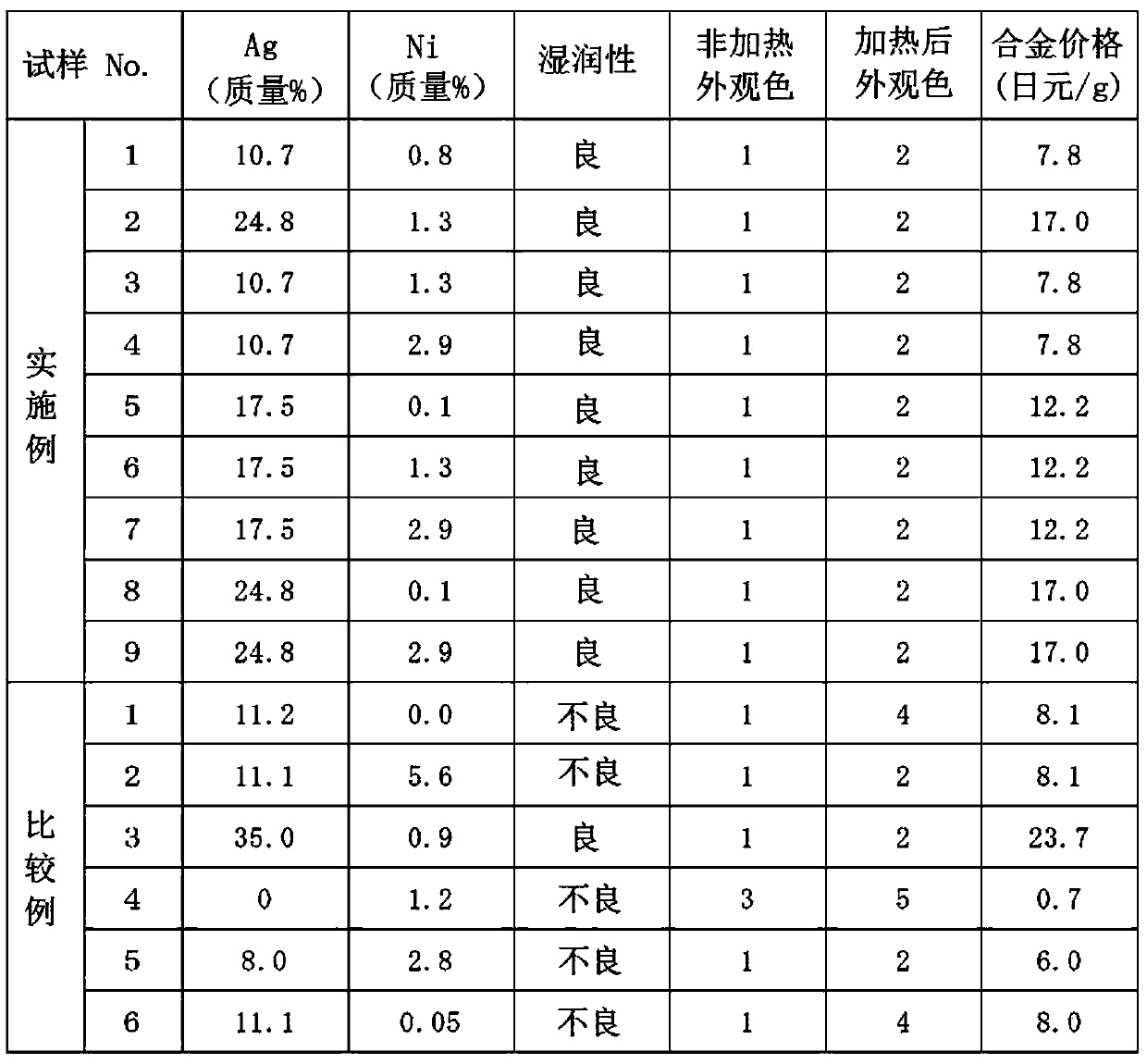
[0049] In Examples and Comparative Examples, copper alloy melts were prepared so as to have the component compositions shown in Table 1 below, and copper alloy samples were produced. In addition, as shown in Table 1, as a component, silver and nickel were contained in predetermined ratios, respectively.

[0050] Specifically, using a high-frequency vacuum melting furnace, after evacuating the cavity to below 0.009Pa, introducing argon gas to 500Pa to produce a copper alloy melt with the composition shown in Table 1 below, at the pressure After being kept under the same conditions for 10 minutes, it was poured into a graphite mold to make an ingot. Then, a disc shape with a thickness of 5 mm and a diameter of 75 mm was cut out from the produced ingot as a copper alloy target, and was used for the following evaluation.

[0051]

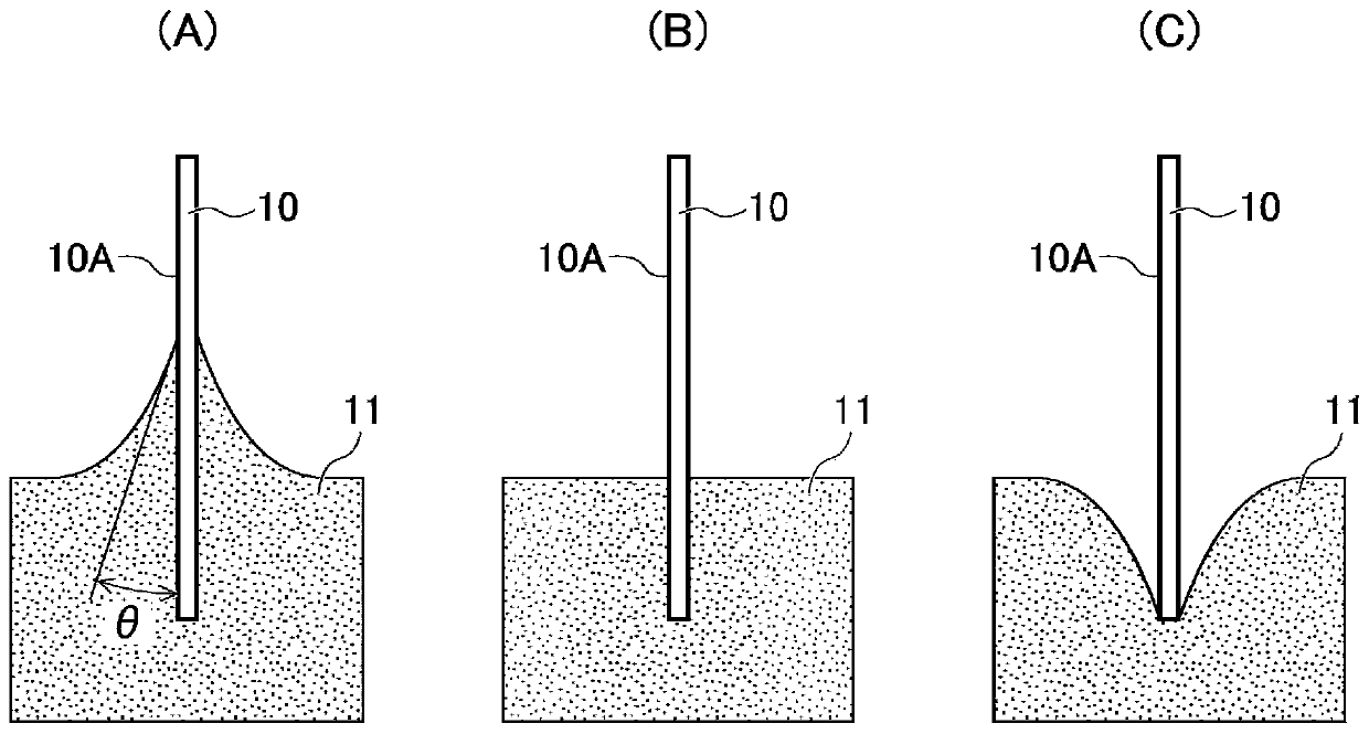
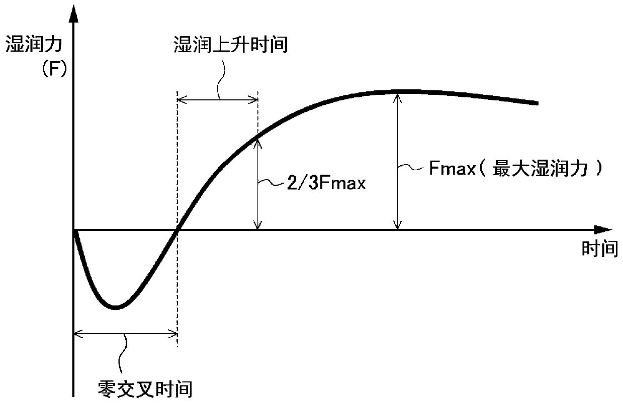
[0052] Using the prepared copper alloy target, a film was formed on a monel plate (Ni-34% by mass Cu) by the sputtering method, and the solder wetta...

manufacture example

[0064] "Manufacturing example (reference example) 2 to 4"

[0065]

[0066] For reference, Manufacturing Example 2 employs the same composition as that of the copper alloy target in Example 1, and the cavity is evacuated and melted in this state. It should be noted that other conditions are the same as in Example 1.

[0067]As a result, silver adhered to the inner side of the inspection window of the cavity, and the inspection window quickly became blurred, and the inside of the cavity could not be observed, and the operation could not be continued. After cooling down, the inside of the chamber was observed, and it was found that silver had adhered not only to the inner wall of the chamber, but also to all parts such as the oscillation coil and electrode terminals, and it was in an unsafe state. It should be noted that the vacuum degree during the melting is 0.4 Pa.

[0068]

[0069] In addition, as Production Example 3, casting was performed with the same composition as...


PUM


Abstract

The present invention provides a copper alloy target for welding electrode film formation capable of forming a copper alloy film at a low price. The sputtering film formation of the copper alloy film does not change color like pure copper film formation, and even after a After treatment with inactive flux, it also shows good solderability and has excellent solder wettability. The copper alloy target for welding electrode film formation according to the present invention contains copper as a main component, contains silver in a ratio of more than 10 mass % to less than 25 mass %, and contains nickel in a ratio of 0.1 mass % to 3 mass %. The copper alloy target is preferably produced in the following manner: after vacuumizing the sealable cavity to below 0.01Pa, introducing an inert gas, adjusting the pressure in the cavity to not less than 50Pa and not more than 90000Pa, and carrying out vacuuming of the metal material. Melting and casting.

Description

technical field [0001] The present invention relates to a copper alloy target used for soldering, for example, electronic components, external electrodes of semiconductor elements, etc., and more specifically, to a copper alloy target for welding electrode film formation, which is used for forming electronic components, Copper alloy film suitable for soldering as the outermost film of the external electrodes of semiconductor elements. Background technique [0002] Generally, when soldering an electronic component, an external electrode of a semiconductor element, or the like, soldering is performed in a state of high wettability with solder to an alloy to be connected. [0003] For example, when the alloy that constitutes the skeleton of the connecting part is Fe-42 mass% Ni alloy (42 alloy), the connecting surface is gold-plated; the alloy is Cu-2.4 mass%Fe-0.03 mass%P-0.12 mass%Zn( alloy 194), tin plating should be carried out in addition to silver plating, or palladium p...

Claims


Application Information

Patent Timeline
Patent Type & Authority Patents(China)
IPC IPC(8): C23C14/34B22D21/00C22B9/04C22C1/02C22C9/00H01L21/285
CPCB22D21/00C22B9/04C22C1/02C22C9/00C23C14/34H01L21/285B22D21/025C23C14/3414H01L2021/60007
Inventor 富樫亮山岸浩一渡边宏幸佐藤惠理子
Owner SUMITOMO METAL MINING CO LTD
Why Eureka
Try Eureka