Double-cavity excitation enhanced microwave plasma torch generation device

A microwave plasma and microwave plasma technology, applied in the field of plasma, can solve the problems of quenching discharge form, constraint, microwave plasma afterglow space extension distance and limited volume, etc., and achieve the effect of increasing the maximum power and good energy coupling effect

Pending Publication Date: 2017-08-22
李容毅
View PDF0 Cites 30 Cited by
  • Summary
  • Abstract
  • Description
  • Claims
  • Application Information

AI Technical Summary

Problems solved by technology

However, at present, only some technical inventions have been proposed in terms of raw material gas injection methods, plasma torch ignition, and application on the basis of existing technologies, and no substantive proposals have been made on how to further improve the energy coupling efficiency and power capacity of plasma. revolutionary technical solutions and inventions
[0003] Microwave plasma operating at high power will not only generate more heat and put forward higher requirements for the cooling and cooling of plasma generating equipment, but also induce various unstable factors under the physical conditions of high energy density. The phenomenon of quenching of plasma discharge and difficult control of discharge form greatly hinders the further improvement of plasma coupling power
In addition, the spatial extension distance and volume of microwave plasma afterglow are limited, which greatly restricts its application.

Method used


Image

  • Double-cavity excitation enhanced microwave plasma torch generation device
  • Double-cavity excitation enhanced microwave plasma torch generation device
  • Double-cavity excitation enhanced microwave plasma torch generation device

Examples


Embodiment Construction

[0029] The specific embodiments of the present invention will be described in detail below in conjunction with the technical solutions and accompanying drawings.

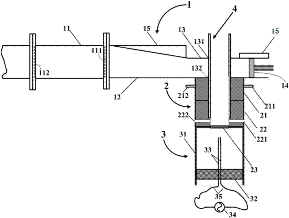
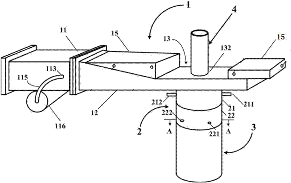
[0030] An enhanced microwave plasma torch generating device with dual-cavity excitation, including a microwave magnetron, a circulator, a directional coupler, a microwave plasma coupling waveguide 1, a cylindrical waveguide 2, an igniter 3 and a discharge tube 4, and a microwave magnetron After the control tube, the circulator, and the directional coupler are connected in series in sequence, the directional coupler is connected to the microwave plasma coupling waveguide 1, which is characterized in that:

[0031] The microwave plasma coupling waveguide 1 comprises a thermal resistance waveguide 11, an impedance converter 12 with tapered waveguide cross-section, a compressed rectangular waveguide 13, a metal short circuit piston 14, water cooling jackets 15 and 16; the metal short circuit piston 14 is located at the s...


PUM


Abstract

The invention relates to a double-cavity excitation enhanced microwave plasma torch generation device, and belongs to the technical field of microwave plasma. The device comprises a microwave magnetron, a circulator, a directional coupler, a microwave plasma coupling waveguide, a cylindrical waveguide, an igniter and a discharge tube. After the microwave magnetron, the circulator and the directional coupler are sequentially connected in series, the directional coupler is connected with the microwave plasma coupling waveguide. The cylindrical waveguide chamber is additionally arranged in the axial direction of the discharge tube perpendicular to a compression rectangular waveguide; a thermal resistance waveguide in the microwave plasma coupling waveguide effectively isolates the influence of thermal release of plasma discharge on a whole system; the igniter makes the whole system operated by a single person to complete a series of processes of ignition, excitation and maintenance, and the ignition success rate is close to 100% under the condition that the no-load output of a microwave source is low. Plasma torch afterglow with a larger volume action area can be obtained by increasing the maximum power of a plasma torch, so that the device can operate stably and reliably for a long time, and can be used in various relevant fields such as combustion assistance, nano material synthesis, waste gas treatment and high-temperature-resistant material surface modification.

Description

technical field [0001] The invention belongs to the technical field of microwave plasma, and provides an enhanced microwave plasma torch generating device with double-cavity excitation. Background technique [0002] After decades of development, thermal plasma technology in the field of low-temperature plasma has been widely used in materials, chemical industry, combustion, military industry and other fields. With the development of microwave technology, the reliability of microwave devices and the energy conversion efficiency of magnetrons have been greatly improved, and the price of microwave components has also been greatly reduced. Using electromagnetic energy in the microwave frequency band to excite and generate plasma, plasma with high density of excited states and active particles can be obtained. Compared with the arc DC torch, because the microwave plasma torch does not use electrodes, it not only prolongs the life of continuous work, but also avoids the pollution...

Claims


Application Information

Patent Timeline
Patent Type & Authority Applications(China)
IPC IPC(8): H05H1/30
CPCH05H1/30
Inventor 李容毅
Owner 李容毅
Why Eureka
Try Eureka