
Pulse plasma thruster based on capillary discharging

A technology of pulsed plasma and plasma, which is applied in the field of plasma thrusters, can solve the problems of low acceleration efficiency of pulsed plasma thrusters, affecting the energy conversion efficiency of thrusters, and low utilization of working fluid, so as to improve energy utilization efficiency , overall safety and reliability improvement, insulation structure simplification effect

Active Publication Date: 2017-08-25
XI AN JIAOTONG UNIV
View PDF5 Cites 13 Cited by
  • Summary
  • Abstract
  • Description
  • Claims
  • Application Information

AI Technical Summary

Problems solved by technology

[0003] 2. The traditional pulse plasma thruster adopts the electromagnetic acceleration mechanism, and the energy storage capacitor is connected through two parallel electrode plates, and the propellant is placed between the two plates.
[0004] 3. Although the electromagnetic pulse plasma thruster uses a solid propellant, the propellant working fluid and the thruster body are combined to form a modular device, but because the electromagnetic force can only accelerate charged particles, it has little effect on the acceleration of neutral molecules
Experiments have shown that the mass of neutral molecules produced by ablation accounts for 70% to 90% of the total ablation product mass, which makes the acceleration efficiency of the pulsed plasma thruster low and affects the overall energy conversion efficiency of the thruster
At the same time, due to the existence of the hysteresis ablation phenomenon and the particle emission effect, the utilization rate of the working medium is low, and there are still great obstacles to the wide application on small power level micro-satellites

Method used


Image

  • Pulse plasma thruster based on capillary discharging
  • Pulse plasma thruster based on capillary discharging

Examples


Embodiment Construction

[0020] Embodiments of the present invention are described in detail below in conjunction with accompanying drawings:

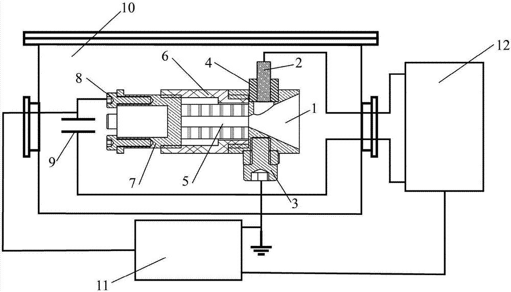
[0021] In one embodiment, the present invention discloses a pulsed plasma thruster based on capillary discharge,

[0022] The thruster includes: a power processing unit, a semiconductor spark plug, an ignition circuit, a main discharge circuit and a propellant working medium;

[0023] The power processing unit is used to provide the voltage required for the thruster to work, charge the main capacitor in the main discharge circuit and supply power to the ignition circuit;

[0024] The ignition circuit is used to output pulse high voltage to cause surface discharge of semiconductor spark plug to generate initial charged particles;

[0025] The initial charged particles generated by the semiconductor spark plug enter the propellant working fluid, and generate plasma through continuous impact ionization;

[0026] The propellant working medium is capillary type, ...


PUM

PropertyMeasurementUnit
The inside diameter ofaaaaaaaaaa
Lengthaaaaaaaaaa
Lengthaaaaaaaaaa

Abstract

The invention relates to a pulse plasma thruster based on capillary discharging. The pulse plasma thruster comprises a power supply processing unit, a main capacitor, a semiconductor sparking plug, an ignition circuit, a main discharging circuit, a propellant working medium, a cathode nozzle, an anode and an organic glass shell. According to the pulse plasma thruster, through introducing the cathode nozzle, main discharging current and the moving direction of plasma form certain angle, and electromagnetic acceleration is introduced under the function of a self-inductance magnetic field. Different from the traditional electromagnetic acceleration type pulse plasma thruster, the pulse plasma thruster based on capillary discharging fully utilizes an electric heating acceleration mechanism to improve the energy utilization efficiency, can improve the overall efficiency of a system under the low-power level, and is particularly suitable for the low-power application site of a microsatellite.

Description

technical field [0001] The disclosure belongs to the field of pulse power technology and power machinery technology, and relates to a pulse plasma thruster based on capillary discharge. Background technique [0002] 1. Traditional cold air propulsion and chemical propulsion systems need to use propellant storage devices and supply systems, which makes the overall mass of the device large and the structure complex. At the same time, the above two propulsion systems have small specific impulse and low efficiency, which largely limits their space applications in microsatellites. Since the former Soviet Union first applied the pulsed plasma thruster to the Zond 2 aircraft in the 1960s, as a new type of electric propulsion system, the pulsed plasma thruster has been greatly developed. And with the expansion of the micro-satellite application market, pulsed plasma thrusters have a wide range of applications in micro-satellites performing high-precision tasks due to their advantag...

Claims


Application Information

Patent Timeline
IPC IPC(8): F03H1/00H01T13/39H01T13/52
CPCH01T13/39H01T13/52F03H1/0006F03H1/0093
Inventor 丁卫东程乐王亚楠闫家启李志闯申赛康
Owner XI AN JIAOTONG UNIV
Learn More