Eureka AIR delivers breakthrough ideas for toughest innovation challenges, trusted by R&D personnel around the world.
Multifunctional local burn dressing change isolation device
What is Al technical title?
Al technical title is built by PatSnap Al team. It summarizes the technical point description of the patent document.
An isolation device and multi-functional technology, applied in the field of medical devices, can solve the problems of single function, unable to control the constant temperature of the patient's burned limb area, and unable to increase the oxygen content of the patient's burned limb area
Inactive Publication Date: 2019-04-30
FOURTH MILITARY MEDICAL UNIVERSITY
View PDF7 Cites 0 Cited by
Summary
Abstract
Description
Claims
Application Information
AI Technical Summary
This helps you quickly interpret patents by identifying the three key elements:
Problems solved by technology
Method used
Benefits of technology
Problems solved by technology
[0004] According to the above, currently existing dressing changing devices are generally simple in structure and single in function, and only have the basic function of raising and supporting limbs. It is impossible to control the constant temperature of the burnt limb area of the patient through the cooling mechanism, so it is easy to cause inflammation of the burn wound and bring hidden dangers to the rehabilitation care of the patient. At the same time, it is well known that the increase of oxygen content can promote wound healing, while the current traditional The traditional dressing changing device cannot improve the oxygen content in the burnt limb area of the patient, which in turn reduces the recovery speed of the patient's burn wound. In view of the above defects, it is necessary to design a multifunctional partial burn dressing change isolation device
Method used
Image
Click on the blue label to locate the original text in one second.
Reading with bidirectional positioning of images and text.
Examples
Embodiment Construction
[0021] In the following, a variety of specific details are explained in order to provide a thorough understanding of the concepts that form the basis of the described embodiments. However, it is obvious to those skilled in the art that the described embodiments can be used without these specific details. Practice in some or all cases, and in other cases, the well-known processing steps are not specifically described.
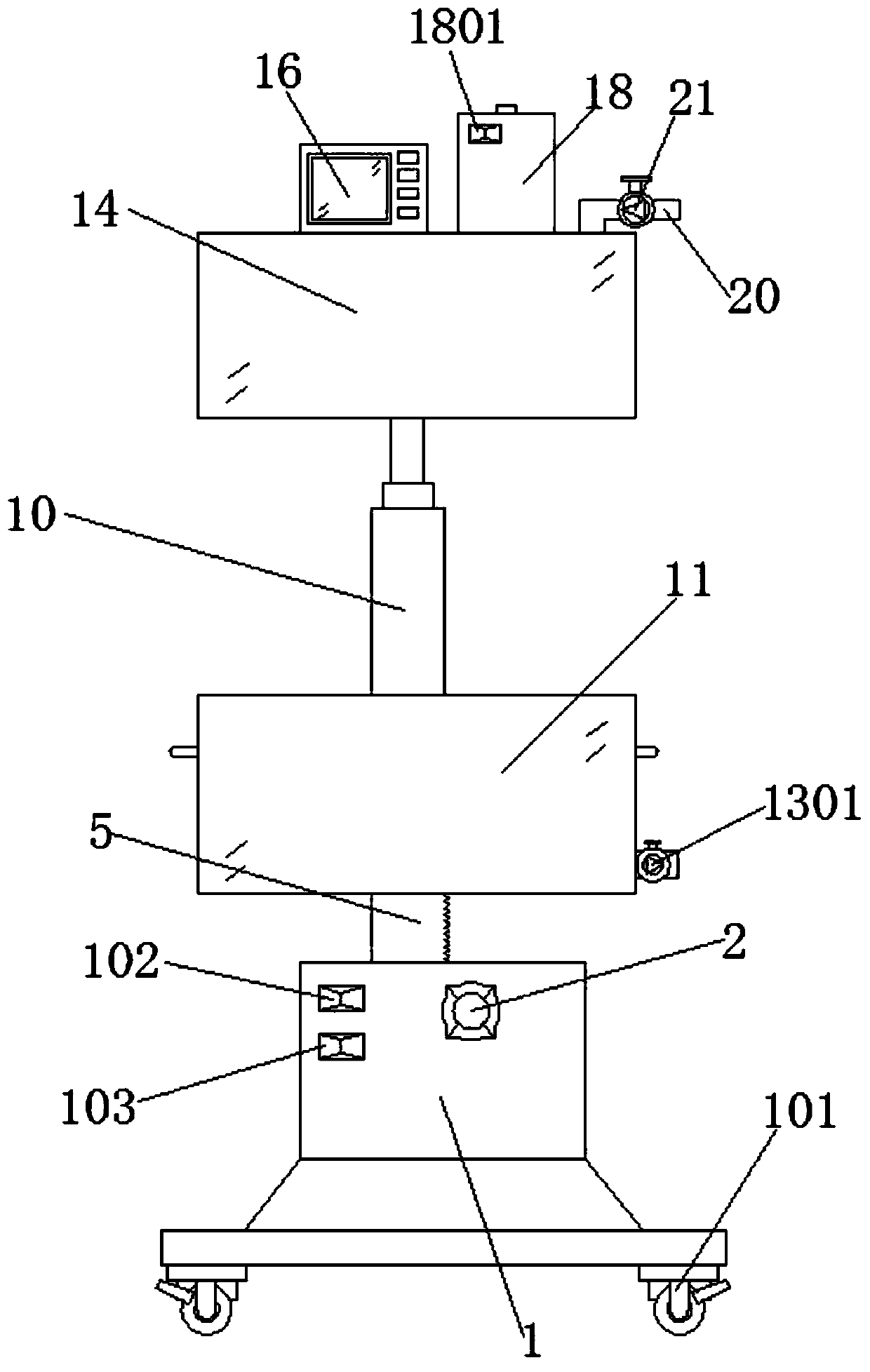
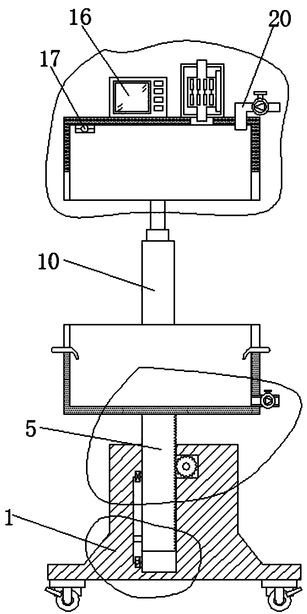
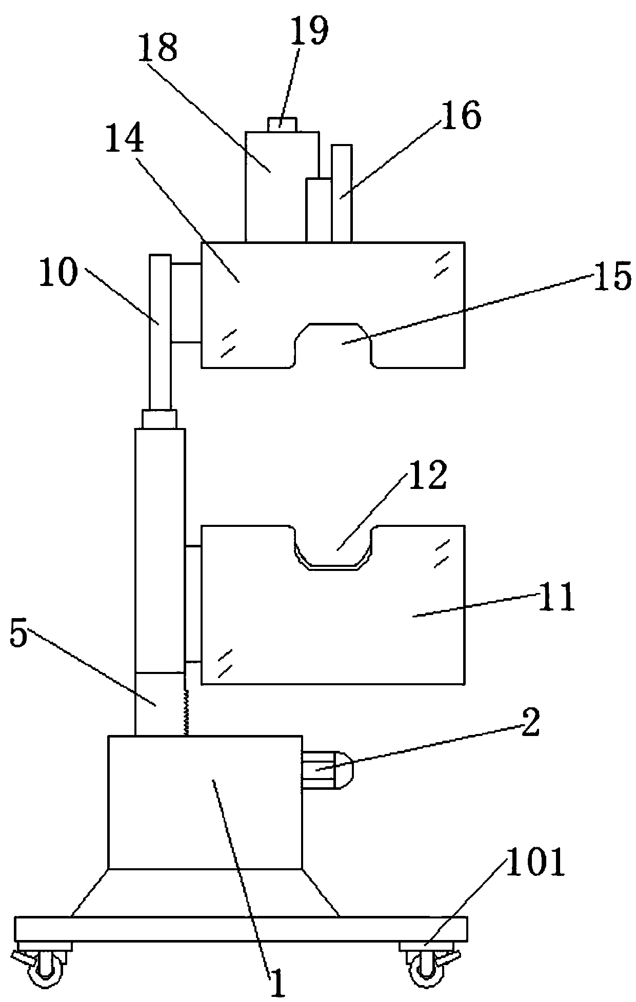
[0022] Such as figure 1 , figure 2 , image 3 , Figure 4 , Figure 5 , Image 6 As shown, the multifunctional partial burn dressing change isolation device includes a base 1, a stepping motor 2, a rotating shaft 3, a gear 4, a rack plate 5, a chute 6, a trigger plate 7, a first travel switch 8, a second travel switch 9. Electric push rod 10, placing box 11, first avoiding slot 12, discharge pipe 13, cover box 14, second avoiding slot 15, thermostat 16, temperature sensor 17, protective cover 18, semiconductor refrigerator 19, connection Tube 20, regulating valve...
PUM
Abstract
The invention discloses a multifunctional local burn dressing change isolating device. The multifunctional local burn dressing change isolating device comprises a base, a stepping motor, a rotating shaft, a gear, a rack plate, a chute, a trigger plate, a first travel switch, a second travel switch, an electric push rod, a placement box, a first pocket groove, a discharge pipe, a cover box, a second pocket groove, a temperature controller, a temperature sensor, a protecting shield, a semiconductor refrigerator, a connecting tube and an adjusting valve. Firstly, a burnt limb of a patient can be supported, isolated and protected, and dressing change of the patient is facilitated; secondly, by a temperature control mechanism, constant-temperature protection on the burnt limb of the patient can be implemented, and wound inflammation caused by high environment temperature is avoided; and finally, the oxygen content of the region of the burnt limb of the patient is increased by simple operation, namely, by increasing of the oxygen content, recovery of the burn wound of the limb of the patient is promoted. Therefore, while the postoperative rehabilitation effect of the patient is greatly improved, clinic operation of medical staff is facilitated, and popularization and application of the medical industry are facilitated.
Description
Technical field [0001] The invention relates to the technical field of medical devices, and in particular to a multifunctional partial burn dressing change isolation device. Background technique [0002] Burns include tissue damage caused by hydrothermal fluid (water, soup, oil, etc.), steam, high-temperature gas, flame, hot metal liquid or solid (such as molten steel, steel ingot), etc. It mainly refers to the skin and / or mucous membrane, and it can also be severe Damage to subcutaneous or / and submucosal tissues, such as muscles, bones, joints and even internal organs. [0003] Generally, burn wounds need to be bandaged after treatment to prevent infection, and several dressing changes are required during the period of healing. At the same time, in the process of dressing changes for patients with burns on limbs, a dressing stand is usually used to assist in lifting the affected limb and facilitate medical care. [0004] According to the above, the existing dressing changing devic...
Claims
Application Information
Patent Timeline
Application Date:The date an application was filed.
Publication Date:The date a patent or application was officially published.
First Publication Date:The earliest publication date of a patent with the same application number.
Issue Date:Publication date of the patent grant document.
PCT Entry Date:The Entry date of PCT National Phase.
Estimated Expiry Date:The statutory expiry date of a patent right according to the Patent Law, and it is the longest term of protection that the patent right can achieve without the termination of the patent right due to other reasons(Term extension factor has been taken into account ).
Invalid Date:Actual expiry date is based on effective date or publication date of legal transaction data of invalid patent.