Supercritical carbon dioxide boiler heating system and heating method

A carbon dioxide and heating system technology, which is applied to fluidized bed boilers, steam boilers, lighting and heating equipment, etc., can solve the problem of insufficient space for the heating surface of the furnace and tail flue, high boiler exhaust gas temperature, and large heat loss of flue gas and other problems to achieve the effect of avoiding high inlet temperature, high equipment integration, and saving floor space

Active Publication Date: 2017-08-29
SHANDONG UNIV
View PDF6 Cites 5 Cited by
  • Summary
  • Abstract
  • Description
  • Claims
  • Application Information

AI Technical Summary

Problems solved by technology

[0004] The boiler is one of the key equipments of the supercritical carbon dioxide Brayton cycle thermal power generation system. For a 300 or 600MW thermal power generation system, the supercritical carbon dioxide Brayton cycle can adopt a reheating recompression cycle process. Under this condition, the supercritical carbon dioxide Boiler design faces many obstacles: First, the temperature of carbon dioxide entering the boiler exceeds 500°C, and its specific heat is lower than that of water vapor, which makes the tube wall of the heating surface in the furnace easy to overheat, and also makes the exhaust gas temperature of the boiler high and the flue gas heat The loss is large; secondly, a large amount of heat recovery is used in the cycle and the low pressure ratio is adopted. The temperature rise of supercritical carbon dioxide in the boiler is small (about 100°C), but the flow rate is much higher than that of the steam boiler under the same heat load, which makes the arrangement of the heating surface different from that of the steam boiler; Finally, supercritical carbon dioxide does not undergo phase change in the boiler, the heat transfer coefficient is low, and the required heat transfer area is large, which will lead to insufficient space for the heating surface of the furnace and tail flue

Method used


Image

  • Supercritical carbon dioxide boiler heating system and heating method

Examples


Embodiment Construction

[0047] It should be pointed out that the following detailed description is exemplary and intended to provide further explanation to the present application. Unless defined otherwise, all technical and scientific terms used herein have the same meaning as commonly understood by one of ordinary skill in the art to which this application belongs.

[0048] It should be noted that the terminology used here is only for describing specific implementations, and is not intended to limit the exemplary implementations according to the present application. As used herein, unless the context clearly dictates otherwise, the singular is intended to include the plural, and it should also be understood that when the terms "comprising" and / or "comprising" are used in this specification, they mean There are features, steps, operations, means, components and / or combinations thereof.

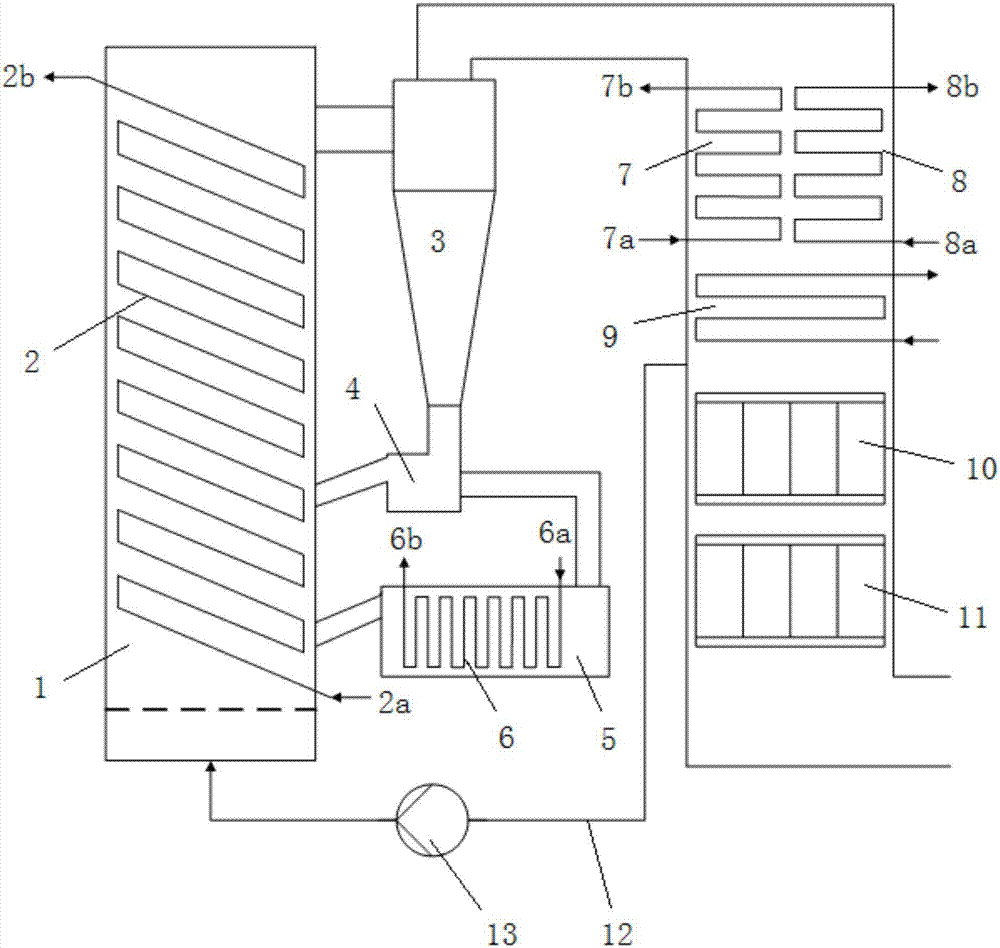
[0049] Such as figure 1 As shown, a supercritical carbon dioxide boiler heating system, the spiral tube coil su...


PUM


Abstract

The invention discloses a supercritical carbon dioxide boiler heating system and a heating method. The supercritical carbon dioxide boiler heating system comprises a boiler, a spiral tube coil superheater, a separator, an external heat exchanger, an external reheater, a flue, a convection superheater and a convection reheater. The spiral tube coil superheater is installed inside a hearth of the boiler and is of a spiral tube coil structure, and a spiral tube coil provides a supercritical carbon dioxide circulating channel. The external reheater is installed inside the external heat exchanger. The convection superheater and the convection reheater are installed inside the flue. The upper end of the hearth communicates with an inlet of the separator. A flue gas outlet of the separator communicates with one end of the flue. A solid particle outlet of the separator communicates with an inlet of the external heat exchanger, and an outlet of the external heat exchanger communicates with the hearth of the boiler. The spiral tube coil superheater and the convection superheater are arranged in parallel. The external reheater and the convection reheater are arranged in parallel.

Description

technical field [0001] The invention belongs to the technical field of high-efficiency thermal power generation, and in particular relates to a supercritical carbon dioxide boiler heating system and a heating method. Background technique [0002] Conventional thermal power generating units work with steam Rankine cycle, and the key determinant of its efficiency is the main steam parameters. At present, the efficiency of the most advanced 700°C supercritical unit can theoretically exceed 50%. However, due to the constraints of existing materials and processes, the improvement of steam parameters has its limits and will lead to a substantial increase in unit cost. How to improve the efficiency of thermal power generation units at the current temperature level has practical and long-term significance for the sustainable development of energy and energy conservation and emission reduction in my country. [0003] The supercritical carbon dioxide Brayton cycle is a new type of hi...

Claims


Application Information

Patent Timeline
Patent Type & Authority Applications(China)
IPC IPC(8): F22B31/00F22B31/08F22G3/00
CPCF22B31/0007F22B31/08F22G3/002Y02E20/34
Inventor 徐震王志强马春元董勇
Owner SHANDONG UNIV
Why Eureka
Try Eureka