
Electric-field-driving molten-metal-spray-forming 3D printing device and working method thereof

A technology of jet deposition and printing device, which is applied in the field of electric field driven molten metal jet deposition 3D printing device, can solve the problems of limited printing materials, low material utilization rate and high printing cost, and achieves rapid heating, good stability and service life. long effect

Inactive Publication Date: 2017-09-01
QINGDAO TECHNOLOGICAL UNIVERSITY
View PDF9 Cites 25 Cited by
  • Summary
  • Abstract
  • Description
  • Claims
  • Application Information

AI Technical Summary

Problems solved by technology

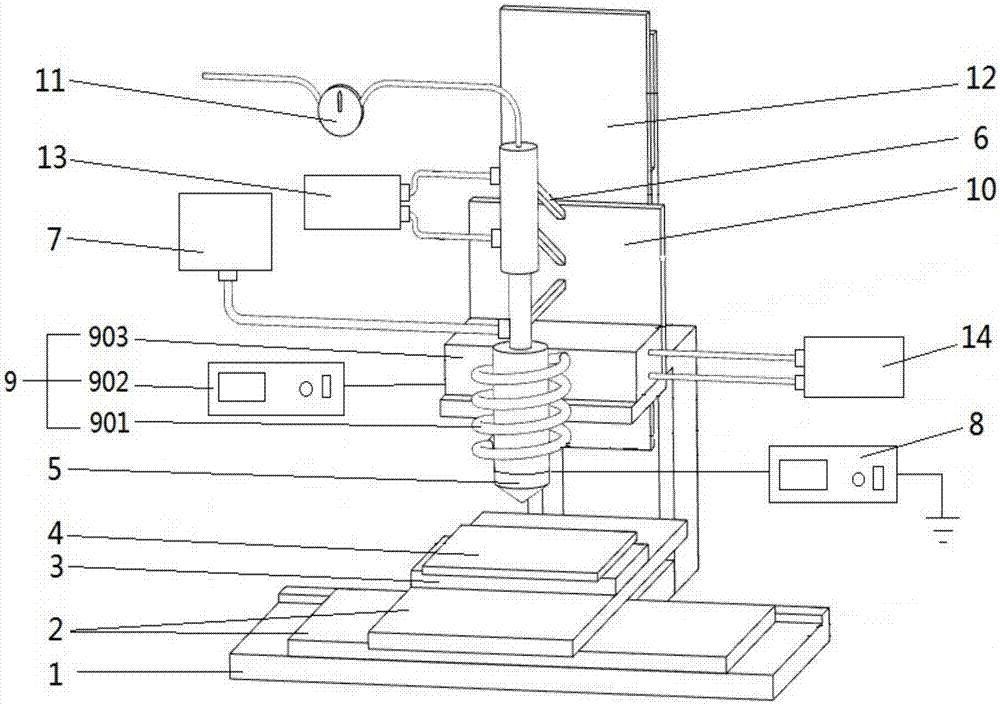
[0007] In order to overcome the shortcomings of the above-mentioned prior art, the present invention provides an electric field driven molten metal spray deposition 3D printing device, which breaks through the existing metal 3D printing equipment and high printing cost, low resolution, low material utilization rate, and complicated manufacturing of printing materials High cost, limited printing materials, difficulty in achieving metal material micro-scale printing and macro / micro cross-scale deficiencies and limitations, especially in combination with multi-nozzle technology and coaxial nozzle technology, can realize multi-scale multi-material structural integration of metal materials 3D printing;

Method used


Image

  • Electric-field-driving molten-metal-spray-forming 3D printing device and working method thereof
  • Electric-field-driving molten-metal-spray-forming 3D printing device and working method thereof
  • Electric-field-driving molten-metal-spray-forming 3D printing device and working method thereof

Examples


Embodiment Construction

[0060] It should be pointed out that the following detailed description is exemplary and intended to provide further explanation to the present application. Unless defined otherwise, all technical and scientific terms used herein have the same meaning as commonly understood by one of ordinary skill in the art to which this application belongs.

[0061] It should be noted that the terminology used here is only for describing specific implementations, and is not intended to limit the exemplary implementations according to the present application. As used herein, unless the context clearly dictates otherwise, the singular is intended to include the plural, and it should also be understood that when the terms "comprising" and / or "comprising" are used in this specification, they mean There are features, steps, operations, means, components and / or combinations thereof.

[0062] As introduced in the background technology, the existing technology has problems of high cost of metal 3D...


PUM


Abstract

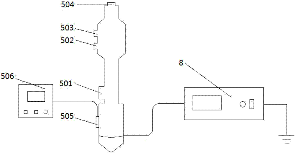
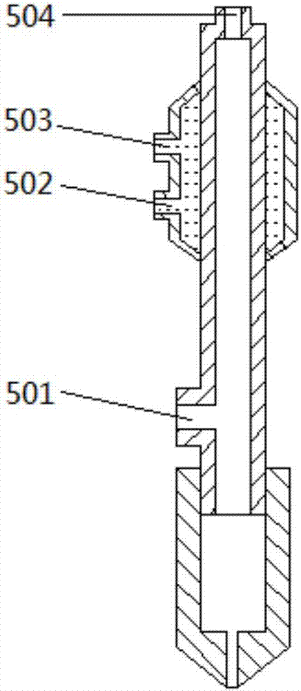
The invention discloses an electric-field-driving molten-metal-spray-forming 3D printing device and a working method thereof. The problems that the cost of metal 3D printing equipment and printing is high, and the resolution ratio is low are solved. A multi-sprayer technology, a coaxial-sprayer technology and the like are combined together, multi-scale and multi-material structurally integrated 3D printing of metal materials can be achieved. According to the technical scheme, the electric-field-driving molten-metal-spray-forming 3D printing device comprises a working table. A printing platform is arranged on the working table, a printing bed is arranged on the printing platform in an absorbed mode, a spraying unit is arranged above the printing bed correspondingly, and the spraying unit is connected with a Z-directional working table; the spraying unit comprises a printing sprayer, the printing sprayer comprises a nozzle and a material-storing barrel which are connected mutually, and the nozzle is connected with the positive pole of a high-voltage pulse power supply; the material-storing barrel is connected with a back pressure control unit and a print-material-supplying unit, and a first water-cooling unit is further arranged between the back pressure control unit and the material-storing barrel; and an electromagnetic induction sprayer heating unit is arranged on the outer portion of the printing sprayer, and the electromagnetic induction sprayer heating unit is connected with a second water-cooling unit.

Description

technical field [0001] The invention relates to the technical fields of additive manufacturing and metal 3D printing, in particular to an electric field-driven molten metal jet deposition 3D printing device and a working method thereof. Background technique [0002] Metal additive manufacturing (3D printing) is currently the most important additive manufacturing technology. It can directly produce functional parts and has a wide range of application values ​​in aerospace, biomedical, automotive, energy, electronics and many other fields. Moreover, there are a wide range of metal materials available for printing, including titanium alloys, high-strength steels, stainless steels, cobalt-chromium-molybdenum alloys, high-temperature alloys, iron, copper alloys, nickel-nickel-based alloys, special alloys for thermonuclear fusion reactors, etc.; Various, including such as Selective Laser Melting (SLM), LENS (Laser Near Net Shape), Selective Laser Sintering (SLS), Laser Metal Fusio...

Claims


Application Information

Patent Timeline
IPC IPC(8): B22F3/115B33Y30/00B33Y10/00
CPCB22F3/115B22F2999/00B33Y10/00B33Y30/00B22F2202/07
Inventor 王飞兰红波周贺飞赵佳伟钱垒邹淑亭
Owner QINGDAO TECHNOLOGICAL UNIVERSITY
Learn More