Gas combustion heating furnace capable of reducing emission of nitrogen oxides and organic volatile matters

A technology of organic volatiles and nitrogen oxides, which is applied in lighting and heating equipment, indirect carbon dioxide emission reduction, burners, etc. Achieve the effects of full mixing and staged combustion, low investment costs, and reduced emissions

Active Publication Date: 2017-09-05
郑州釜鼎热能技术有限公司
View PDF5 Cites 7 Cited by
  • Summary
  • Abstract
  • Description
  • Claims
  • Application Information

AI Technical Summary

Problems solved by technology

[0004] As mentioned above, in order to overcome the defects of the prior art, the object of the present invention is to provide a gas combustion heating furnace that reduces the emission of nitrogen oxides and organic volatiles, which can effectively solve the problem of nitrogen oxides (NOx) and organic volatiles in gas combustion heating furnaces. Volatile matter (VOC) emissions are large, not up to standard, serious environmental pollution problems

Method used


Image

  • Gas combustion heating furnace capable of reducing emission of nitrogen oxides and organic volatile matters
  • Gas combustion heating furnace capable of reducing emission of nitrogen oxides and organic volatile matters
  • Gas combustion heating furnace capable of reducing emission of nitrogen oxides and organic volatile matters

Examples


Embodiment Construction

[0013] The specific implementation manners of the present invention will be described in detail below in conjunction with the accompanying drawings.

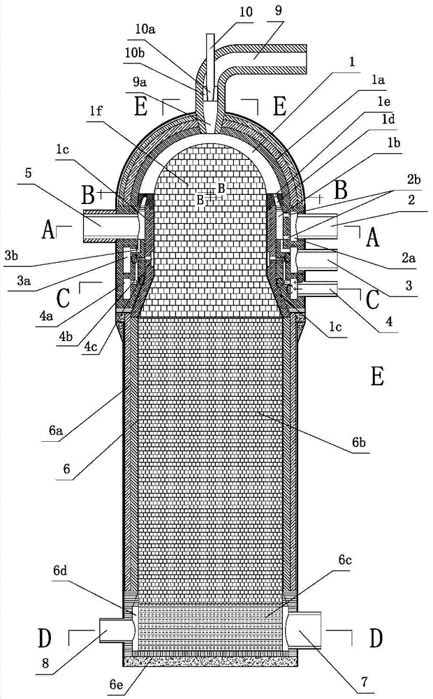
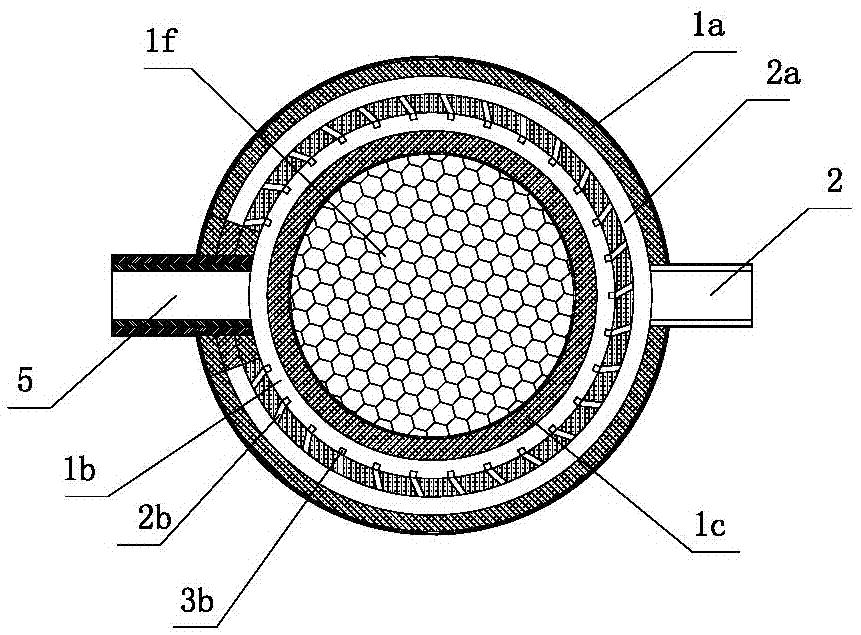
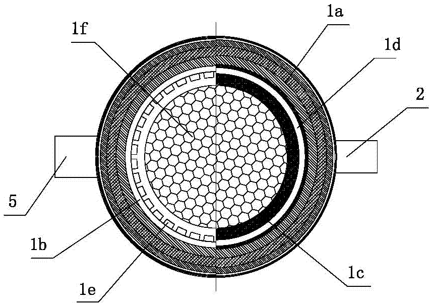
[0014] Depend on Figure 1-Figure 6Given, the structure of the present invention is that the premixed prechamber 1 is the inner space of the lower opening of the premixed prechamber wall 1a formed by butting the upper hemispherical vault and the lower cylindrical wall, The inner side of the cylindrical wall is provided with a shrinking ring wall 1c, and the inner wall of the shrinking ring wall has a secondary air guide ring groove 4c connected with the premixed pre-combustion chamber, and the upper part between the shrinking ring wall and the cylindrical wall is set There is a mixed diversion ring 1b, and the top of the mixed diversion ring has a progressively shrinking annular gap 1d upwards, and the top of the annular gap is evenly distributed around the top of the annular gap with mixed gas nozzles 1e communicating with the ...


PUM


Abstract

The invention relates to a gas combustion heating furnace capable of reducing emission of nitrogen oxides and organic volatile matters, and the gas combustion heating furnace effectively solves the problem that emission amount of nitrogen oxides and organic volatile matters of the heating furnace is great, and the emitted nitrogen oxides and organic volatile matters do not reach the standard. A guide ring slot is formed in a ring wall in a pre-combustion chamber wall body; a spray hole is formed in the top of a gap in the guide ring path between the ring wall and the wall body; a hot gas tube, a fuel gas tube, an air tube and a secondary air tube are arranged outside the wall body; distributing ring paths which are connected with the fuel gas tube, the air tube and the secondary air tube are arranged in the inner wall of the wall body; the hot gas tube is connected with the guide ring path; a fuel gas spray nozzle, an air spray tube and a secondary air spray nozzle tube are arranged on each distributing ring path; the lower part of a pre-combustion chamber is equipped with a heat storage chamber; a heat storage body is arranged in each of the ring wall and the heat storage chamber; a flue gas and cold gas tube is arranged on the wall body of the heat storage chamber; a collecting ring slot is formed between the flue gas and cold gas tube and the heat storage body; a reflux spray nozzle on the top of the wall body of the pre-combustion chamber is connected with a reflux tube; an injection tube is arranged in the reflux tube; and a supporting plate is arranged between a spray hole of the ejection tube and the reflux tube. The gas combustion heating furnace effectively inhibits generation of nitrogen oxides and control of organic volatile matters, is simple in structure, and saves investment cost.

Description

technical field [0001] The invention relates to thermal equipment of the heating furnace type, especially a thermal device for providing process hot air flow for industrial furnaces such as carbonization furnaces, drying furnaces, and incinerators, belonging to industrial furnaces, especially a kind of equipment for reducing nitrogen oxides and organic compounds. Gas-fired furnaces emitting volatiles. Background technique [0002] For the regenerative heating furnace that uses the gas combustion gas flow to heat the porous regenerator and the cold gas flow to cool the porous regenerator to generate high-temperature hot gas flow, the combustion process of gas gas and the cycle of gas gas and porous body The heat transfer process of permanent heat storage and heat release will directly affect the working performance of the heating furnace. With the advancement of modern industrial technology, higher technical requirements have been put forward for heating furnaces, which are ...

Claims


Application Information

Patent Timeline
Patent Type & Authority Applications(China)
IPC IPC(8): F23D14/02F23D14/64F23D14/66F23M5/06F23M5/00
CPCF23D14/02F23D14/64F23D14/66F23M5/00F23M5/06Y02E20/34
Inventor 陈维汉陈云鹤杨海涛张佳鹏
Owner 郑州釜鼎热能技术有限公司
Why Eureka
Try Eureka