
Gasification unit for preparing biomass medium-heating value fuel gas

A gasification device and biomass technology, applied in the manufacture of combustible gas, petroleum industry, etc., can solve the problems of abnormal reaction, high cost and high calorific value, etc.

Active Publication Date: 2017-09-15
NANJING FORESTRY UNIV
View PDF3 Cites 2 Cited by
  • Summary
  • Abstract
  • Description
  • Claims
  • Application Information

AI Technical Summary

Problems solved by technology

Many scientific research institutes have conducted research on the denitrification of combustible gas, and have realized the denitrification of combustible gas, but due to the high cost, it cannot be industrialized
Oxygen is used as the gasification agent. Due to high cost and safety issues, its production technology is still in the research stage in the laboratory
Air is used as the gasification agent, and water vapor is injected to increase the calorific value of the gas. This technology has been applied in coal gasification, but air and water vapor are sprayed into the furnace separately. Due to the high calorific value of coal, the temperature of the reaction layer is high. , the separate injection of air and water vapor will not affect the reaction of the reaction layer, but the calorific value of biomass is much lower than that of coal. If coal is used, separate steam injection and uneven gas distribution will lead to The reaction temperature drops sharply, and the reaction cannot proceed normally

Method used


Image

  • Gasification unit for preparing biomass medium-heating value fuel gas
  • Gasification unit for preparing biomass medium-heating value fuel gas
  • Gasification unit for preparing biomass medium-heating value fuel gas

Examples


Embodiment Construction

[0024] The present invention will be further described below in conjunction with the accompanying drawings.

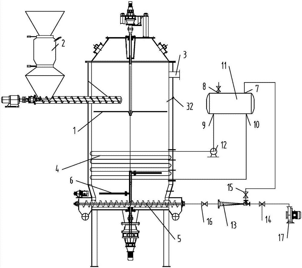
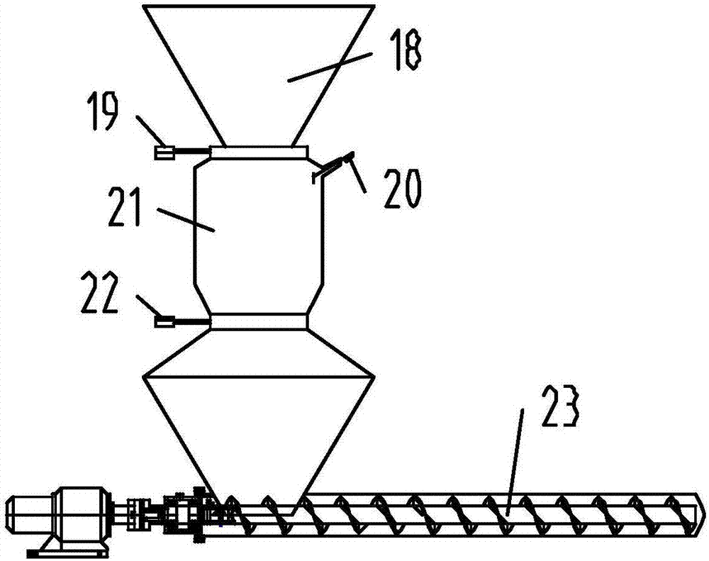
[0025] Control attached figure 1 In the shown gasification device for preparing biomass combustible gas with medium calorific value, a spreader 1 driven by a reducer is installed on the upper part of the gasifier to spread the gasification raw material in the closed feeding device 2, and the The airtight feeding device 2 controls its feeding according to the material level meter 32 installed on the gasifier body. A heating coil 4 is arranged on the furnace wall 300 mm above the spiral discharge gas distribution device 5. A breaker is installed at the lower part of the furnace body. The bridge device 6 is used to prevent bridging of the reaction layer.

[0026] The steam generation intake system is composed of a steam drum 11, a circulating hot water pump 12, a mixer 13, valves, a fan 17 and the like. The steam drum 11 is provided with a water supply port 8 , a water ...


PUM


Abstract

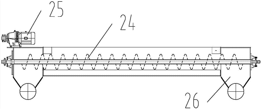
The invention provides a gasification unit for preparing biomass medium-heating value fuel gas, which can improve the heating value of gasified combustible gas on the basis of not additional investment of big production devices and guarantee of stable running. The gasification unit comprises a gasification furnace and a steam generation air inlet system; the bottom part of the gasification furnace is provided with a spiral discharging gas distribution device, and a spiral shaft rotated in the spiral discharging gas distribution device is a hollow shaft of which periphery is provided with a spiral blade; an air outlet is arranged on the hollow shaft; the steam generation air inlet system comprises a steam pocket, a circular hot water pump, a heating coil arranged at the middle lower part of the gasification furnace, a mixer, a blower and a valve; a heating coil outlet is connected with a water inlet of the steam pocket through the circular hot water pump, and the water outlet of the steam pocket is connected with the heating coil inlet; a vapor outlet of the steam pocket is connected to an inlet of the mixer through the valve; a blower outlet is connected to the inlet of the mixer through the valve; the mixer outlet is connected with one end of the spiral shaft through a rotating joint.

Description

technical field [0001] The invention relates to a gasification device for preparing biomass combustible gas with medium calorific value, and belongs to the field of biomass energy. Background technique [0002] In the current biomass gasification technology, the gasification agent used in the industrial production of the gasification device is mainly air, because the air contains a large amount of nitrogen that does not participate in the gasification reaction, and finally enters the combustible gas, making the biomass gasification combustible gas The calorific value is between 950kcal-1250kcal depending on the gasification raw material, and its calorific value is relatively low. It can only be used for low-temperature and low-pressure boilers for boiler combustion because the calorific value is too low; it can only be used for low-speed internal combustion generators for internal combustion engine power generation. It is used for residents' cooking. Due to the low calorific...

Claims


Application Information

Patent Timeline
Patent Type & Authority Applications(China)
IPC IPC(8): C10J3/20C10J3/32
Inventor 周建斌章一蒙马欢欢张齐生
Owner NANJING FORESTRY UNIV
Learn More