
Melting furnace containing anti-blockage heat storage device

A regenerative and melting furnace technology, which is applied in the field of melting furnaces and anti-clogging regenerative devices, can solve the problem that ceramic ball fragments and dust block the honeycomb regenerator, and the regenerative combustion device has different combustion conditions and high temperature. The problem of unsatisfactory dust removal effect of flue gas can achieve significant energy saving effect, improve melting efficiency and no heat loss.

Pending Publication Date: 2017-09-15
SHENWU TECH GRP CO LTD
View PDF0 Cites 0 Cited by
  • Summary
  • Abstract
  • Description
  • Claims
  • Application Information

AI Technical Summary

Problems solved by technology

[0006] At present, due to the different design and layout of combustion devices, the smelting equipment using regenerative gas heating generally suffers from poor smoke exhaust, high pressure in the furnace, difficulty in meeting the reducing atmosphere required by the process, and high exhaust gas temperature. high-level problems; moreover, the heat supply of the existing smelting equipment using regenerative gas heating is unstable, which is manifested by the different combustion conditions of the symmetrically arranged regenerative combustion devices; in addition, when the high-temperature dusty flue gas passes through the regenerator, the high The thermal storage carrier ceramic ball in the area bursts, the dust removal effect of high-temperature flue gas is not ideal, and ceramic ball fragments and dust block the honeycomb heat storage body and other problems often occur.

Method used


Image

  • Melting furnace containing anti-blockage heat storage device
  • Melting furnace containing anti-blockage heat storage device
  • Melting furnace containing anti-blockage heat storage device

Examples


Embodiment Construction

[0034] Embodiments of the present invention are described in detail below, examples of which are shown in the drawings, wherein the same or similar reference numerals designate the same or similar elements or elements having the same or similar functions throughout. The embodiments described below by referring to the figures are exemplary only for explaining the present invention and should not be construed as limiting the present invention.

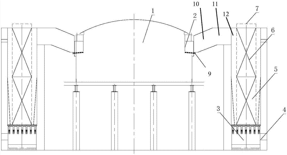
[0035] According to an embodiment of the present invention and the figure 1 , showing a melting furnace with an anti-clogging regenerative device, comprising:

[0036] Furnace body 1, the upper part of the furnace body is provided with a pair of furnace body gas circulation ports 2;

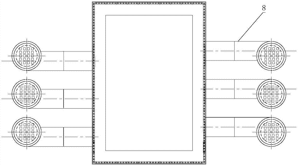
[0037] A pair of heat storage devices, the heat storage device includes a shell, a heat storage body, and a settling chamber 3. The inside of the shell is provided with an outer ring channel and a central channel that are not directly connected in sequence...


PUM


Abstract

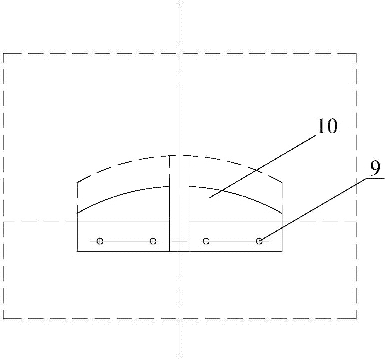
The invention discloses a melting furnace containing an anti-blockage heat storage device. The melting furnace comprises a furnace body, a heat storage device and a connecting channel, wherein a furnace body gas circulating port is formed in the upper part of the furnace body; the heat storage device comprises a shell, a heat storage body and a settling chamber; an outer ring channel and a center channel for not directly conducting are arranged in the shell in sequence from outside to inside; a first opening for communicating with the outer ring channel is formed in the upper part of the shell; a second opening is formed in the upper end of the center channel; the heat storage body is arranged in the center channel; the settling chamber is positioned under the heat storage body; the center channel and the outer ring channel respectively communicate with the settling chamber; and two ends of the connecting channel are respectively connected with the furnace body gas circulating port and the first opening. A heat storage chamber of the device integrates a cyclone dust removing function, and is excellent in blockage preventing performance, compact in system, low in heat energy loss and long in service life of the heat storage body; and the corresponding melting furnace can satisfy reductive atmosphere needed by technological melting to achieve high heat efficiency.

Description

technical field [0001] The invention relates to the field of energy saving and environmental protection, in particular to an anti-blocking regenerative device and a melting furnace equipped with the device. Background technique [0002] The important defects in the current regenerative combustion technology are mainly reflected in the honeycomb regenerator, the key component of the regenerative burner. During the use of the regenerative burner, the heat storage body and the air flow exchange heat, and some corrosive gases and particulate dust will have an adverse effect on the heat storage body, causing problems such as blockage, corrosion and rupture to occur frequently , so that the burner cannot work normally. For example, iron oxide particles will reduce the reflow temperature of aluminum-silicon material, causing the regenerator to melt and block the pores; acid gas will corrode the regenerator; tiny particles will adhere to the surface of the regenerator and block the...

Claims


Application Information

Patent Timeline
Patent Type & Authority Applications(China)
IPC IPC(8): F27D17/00F23D14/66
CPCF23D14/66F27D17/004F27D17/008F27D2017/007F27M2003/13Y02E20/34
Inventor 钟贵全郭科宏王东方王志军石为华陈珊杨玉地宋敏洁吴道洪
Owner SHENWU TECH GRP CO LTD
Learn More