Adaptive bias circuit with low loss and temperature compensation, and wireless transmitting system

An adaptive bias and temperature compensation technology, which is applied in the direction of improving the amplifier to reduce temperature/power supply voltage changes, transmission systems, amplifiers with semiconductor devices/discharge tubes, etc., can solve the problem of power amplifier efficiency reduction, power tube Q1 current Consumption, power tube Q1 temperature rise and other issues, to achieve the effects of low device cost, improved thermal performance, and easy implementation

Active Publication Date: 2017-09-15
GUANGDONG UNIV OF TECH
View PDF3 Cites 13 Cited by
  • Summary
  • Abstract
  • Description
  • Claims
  • Application Information

AI Technical Summary

Problems solved by technology

Obviously, in the above method, the bias circuit can improve the linearity of the power amplifier, however, when Q20 is turned on, the current I of the collector of Q20 C,Q20 supplied directly to the base of Q1, to maintain V P Stabilized at the DC potential, when the input signal increases, the current I of the collector of Q20 C,Q20 It will also increase sharply, which will cause the power tube Q1 to have a very large current consumption, resulting in a decrease in the efficiency of the power amplifier
in addition, figure 1 In the bias circuit shown, the power tube Q1 has a negative temperature coefficient that becomes smaller as the temperature is higher. When the circuit draws a large amount of load current, the heating caused by the loss of the collector causes the temperature of the power tube Q1 to rise, causing the power tube Q1 overheating problem

Method used


Image

  • Adaptive bias circuit with low loss and temperature compensation, and wireless transmitting system
  • Adaptive bias circuit with low loss and temperature compensation, and wireless transmitting system
  • Adaptive bias circuit with low loss and temperature compensation, and wireless transmitting system

Examples


Embodiment Construction

[0024] The following will clearly and completely describe the technical solutions in the embodiments of the present invention in conjunction with the accompanying drawings in the embodiments of the present invention. Obviously, the described embodiments are only some of the embodiments of the present invention, not all of them. Based on the embodiments of the present invention, all other embodiments obtained by persons of ordinary skill in the art without making creative efforts belong to the protection scope of the present invention.

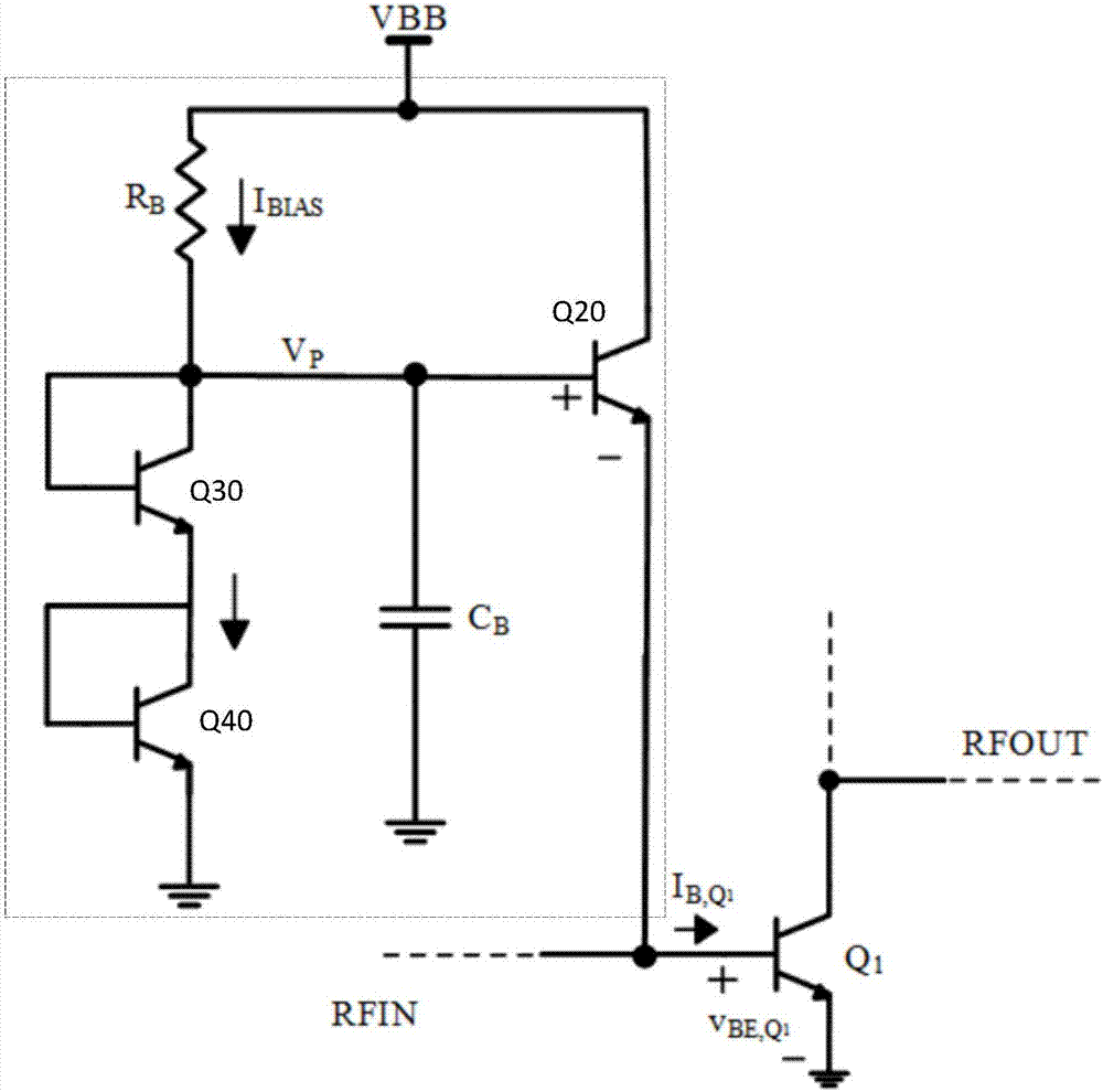
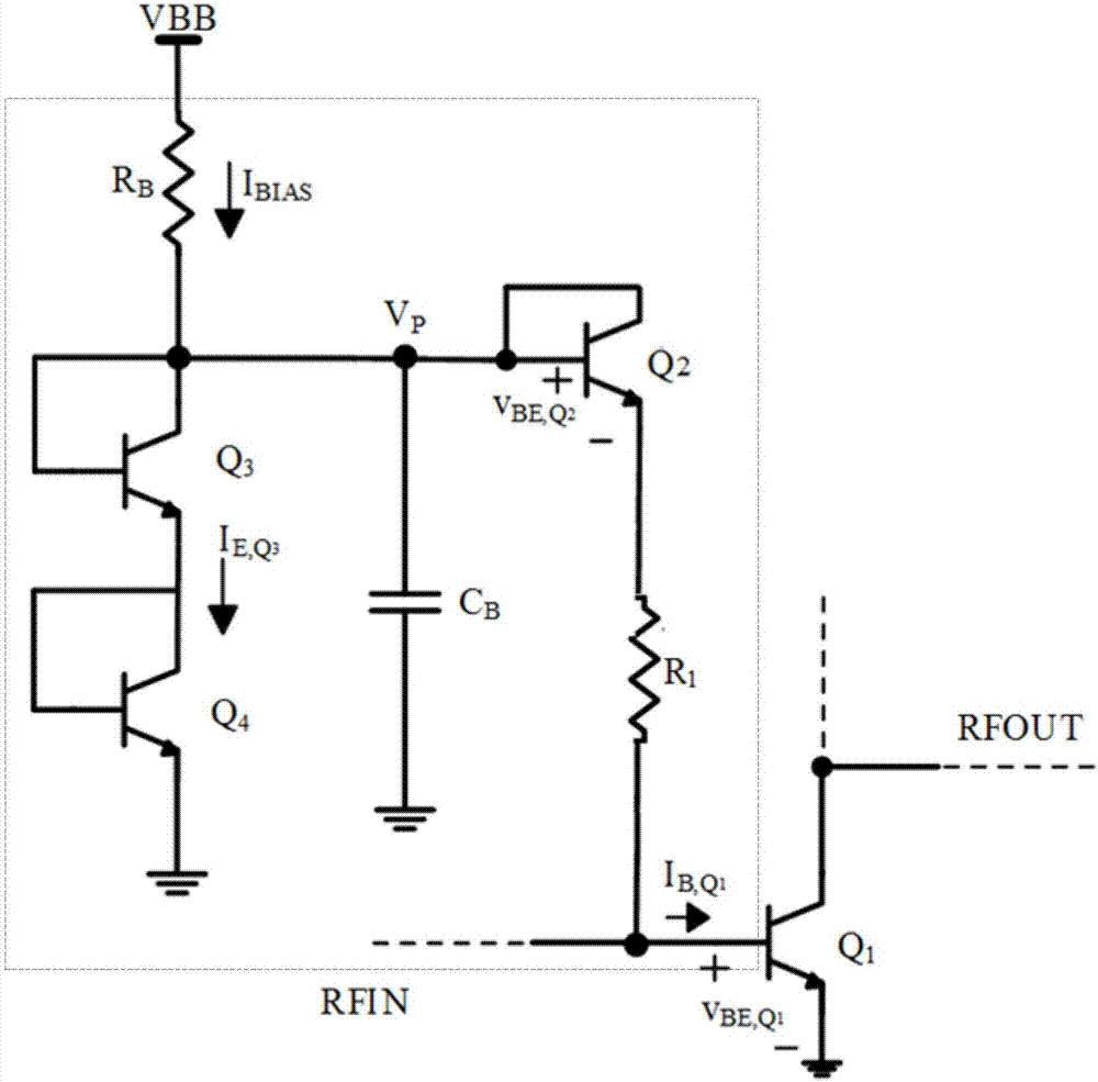
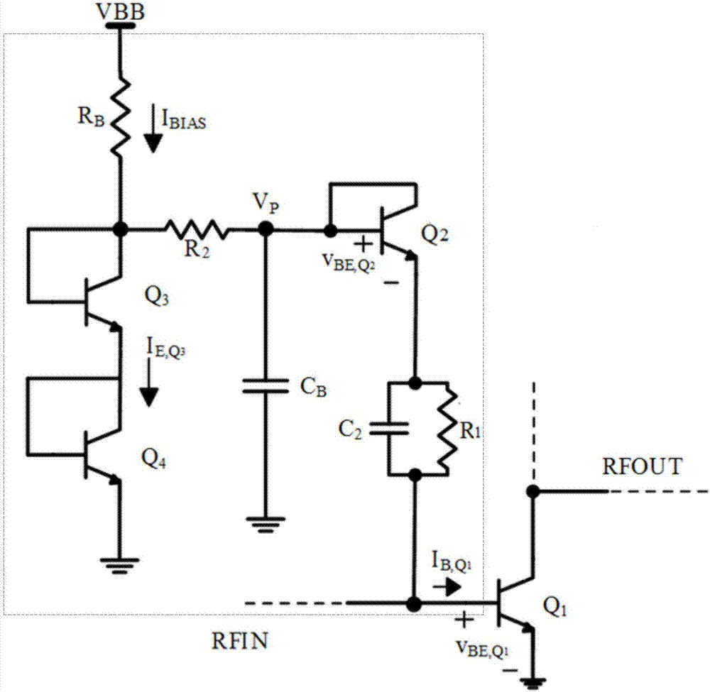
[0025] The core of the present invention is to provide an adaptive bias circuit with low loss and temperature compensation and a wireless transmission system, which are used to achieve the balance between efficiency and linearity of the power amplifier and to suppress the temperature rise of the power tube.

[0026] In order to enable those skilled in the art to better understand the solution of the present invention, the present invention will ...


PUM


Abstract

The invention discloses an adaptive bias circuit with low loss and temperature compensation. The adaptive bias circuit comprises a first NPN type triode having a current mirror structure, a second NPN type triode, a transistor, a bias capacitor and a first resistor. By means of a specific circuit connecting structure, the potential of the bias capacitor can be kept unchanged when the input power is increased and does not exceed the critical value, therefore the current of the collector of a power tube is increased with the increase of the input power, and when the input power is further increased and exceeds the critical value, the potential of the bias capacitor is reduced, therefore the current of the collector of the power tube is reduced with the increase of the input power and finally trends to be stable. In addition, the temperature of the power tube can be compensated by the first resistor to improve the thermal temperature. The invention further discloses a wireless transmitting system comprising the above circuit, and the beneficial effects are as mentioned above.

Description

technical field [0001] The invention relates to the technical field of power amplifiers, in particular to an adaptive bias circuit with low loss and temperature compensation and a wireless transmission system. Background technique [0002] The power amplifier plays an important role in wireless communication systems not only because it determines the performance of the system, but also because it is the most energy-consuming component, generating a lot of noise and heat. High-efficiency power amplifiers are designed to improve battery life in wireless end devices with limited battery capacity. A high-efficiency power amplifier requires the power tube to have a low turn-on voltage, a high breakdown voltage and work in a state close to saturation. The bias point and load line of a traditional power amplifier are optimally designed according to the 1dB compression point (P1dB), so that the efficiency of the power amplifier is optimal at the maximum output power. But in actual...

Claims


Application Information

Patent Timeline
Patent Type & Authority Applications(China)
IPC IPC(8): H03F1/30H03F1/32H03F1/02H03F3/21H03F3/24H04B1/04
CPCH03F1/0205H03F1/302H03F1/32H03F3/21H03F3/245H04B1/04H04B2001/0416Y02D30/70
Inventor 蔡秋富章国豪
Owner GUANGDONG UNIV OF TECH
Why Eureka
Try Eureka