
High-speed electro-optical modulator and preparation method thereof

An electro-optical modulator and high-speed technology, applied in the field of optical communication, can solve the problems of low signal-to-noise ratio, slow modulation speed, and high cost of electro-optical modulators, and achieve high signal-to-noise ratio, low optical signal loss, and efficient and fast modulation speed. Effect

Pending Publication Date: 2017-09-19
LASER FUSION RES CENT CHINA ACAD OF ENG PHYSICS
View PDF5 Cites 0 Cited by
  • Summary
  • Abstract
  • Description
  • Claims
  • Application Information

AI Technical Summary

Problems solved by technology

The usual electro-optic modulators use certain electro-optic crystals, such as lithium niobate crystals (LiNbO 3 ), gallium arsenide crystal (GaAs) and lithium tantalate crystal (LiTaO 3 ) modulators made of the electro-optic effect, but these types of electro-optic modulators have high cost, slow modulation speed, and low signal-to-noise ratio, so how to prepare electro-optic modulators with better performance and more economical price is of great importance. meaningful

Method used


Image

  • High-speed electro-optical modulator and preparation method thereof
  • High-speed electro-optical modulator and preparation method thereof

Examples


Embodiment 1

[0036] A method for preparing a high-speed electro-optic modulator includes the following steps:

[0037] Step 1: Wind two SMF28 single-mode fibers together, put them into the fiber drawing platform and draw them into a micro-nano fiber coupler with a lateral width of 6μm;

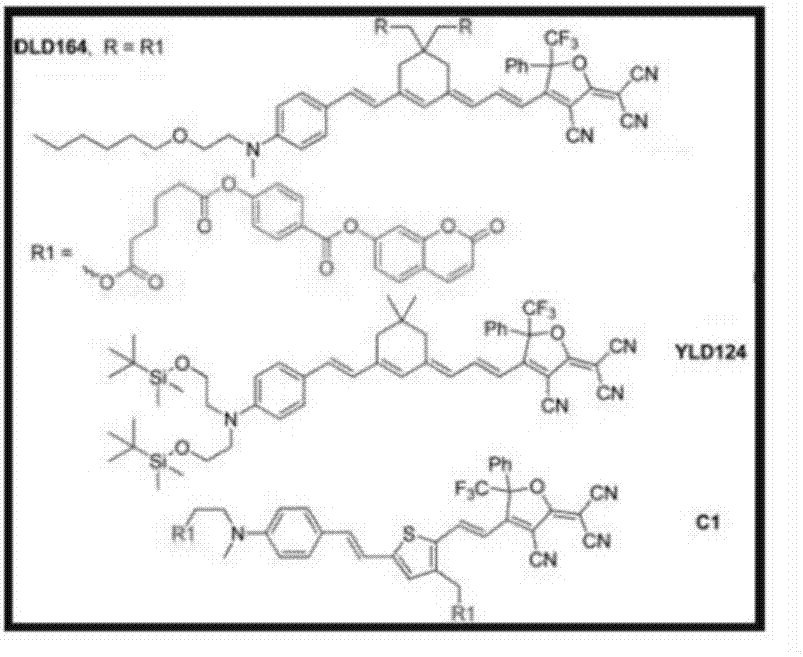
[0038] Step 2: Put the micro-nano fiber coupler into the second-order nonlinear light emitting group material layer (DLD164, R=R1) in acetone solution, and use the pulling coating method to coat the surface with a thickness of 200nm at a speed of 500mm / min The second-order nonlinear light emitting group material layer (DLD164, R=R1);

[0039] Step 3: Put the micro-nano fiber coupler coated with the second-order nonlinear light emitting group material layer (DLD164, R=R1) in the middle of the ITO electrode with a distance of 4mm for polarization, and the polarization voltage is 10000V, and the entire electrode Put the polarization device in a thermostat, heat the polarization device to 135°C, maintain the polariz...

Embodiment 2

[0042] A method for preparing a high-speed electro-optic modulator includes the following steps:

[0043] Step 1: Twist two SMF28 single-mode fibers together, put them into the fiber drawing platform and draw them into a micro-nano fiber coupler with a lateral width of 4μm;

[0044] Step 2. Put the micro-nano fiber coupler into the second-order nonlinear light emitting group material layer (DLD164, R=R1) in acetone solution, and use the pulling coating method to coat the surface with a thickness of 70nm at a speed of 100mm / min The second-order nonlinear light emitting group material layer (DLD164, R=R1);

[0045] Step 3: The micro-nano layer coated with the second-order nonlinear light emitting group material layer (DLD164, R=R1)

[0046] The fiber coupler is placed in the middle of the ITO electrode with a distance of 2mm for polarization, and the polarization voltage is 8000V. At the same time, the entire polarization device is placed in a thermostat, and the polarization device is ...

Embodiment 3

[0048] A method for preparing a high-speed electro-optic modulator includes the following steps:

[0049] Step 1: Twist two SMF28 single-mode fibers together, put them into the fiber drawing platform and draw them into a micro-nano fiber coupler with a lateral width of 3μm;

[0050] Step 2. Put the micro-nano fiber coupler into the second-order nonlinear light emitting group material layer (DLD164, R=R1) in acetone solution, and use the pulling coating method to coat the surface with a thickness of 120nm at a speed of 300mm / min The second-order nonlinear light emitting group material layer (DLD164, R=R1);

[0051] Step 3: The micro-nano layer coated with the second-order nonlinear light emitting group material layer (DLD164, R=R1)

[0052] The fiber coupler is placed in the middle of the ITO electrode with a distance of 3mm for polarization, and the polarization voltage is 900V. At the same time, the entire polarization device is placed in a thermostat, and the polarization device is ...


PUM

PropertyMeasurementUnit
widthaaaaaaaaaa
thicknessaaaaaaaaaa
thicknessaaaaaaaaaa

Abstract

The invention discloses a high-speed electro-optical modulator, which comprises a micro nano optical fiber coupler, a high polymer electro-optic material layer and a plate electrode, wherein the micro nano optical fiber coupler is prepared by intertwining two single mode optical fibers and drawing into a fiber drawing platform, the high polymer electro-optic material layer is coated on the micro nano optical fiber coupler, and the plate electrode is butted against the outside of the high polymer electro-optic material layer. The preparation method of the novel high-speed electro-optical modulator, disclosed by the invention, can efficiently and rapidly prepare an electro-optical modulator with rapid modulation, less optical signal loss, high signal-to-noise ratio and low cost. When the laser from a semiconductor laser is injected into the device from the input end of the electro-optical modulator, and the electrode applies an electrical signal to the two ends of the plate electrode, the unit surface refractive index is changed, resulting in change in synchronous resonant wavelength, which affects the change of the output port optical power, and ultimately an optical signal with the consistent change with the electrical signal is obtained. The high-speed electro-optical modulator disclosed by the invention can be used in the field of optical communication, and the problems of the common electro-optical modulator in the prior art are solved, including high cost, slow modulation and low signal-to-noise ratio.

Description

Technical field [0001] The invention belongs to the field of optical communication technology, and specifically relates to a novel high-speed electro-optic modulator and a preparation method thereof. Background technique [0002] Optical fiber communication has quickly become the main form of information transmission today due to its advantages such as bandwidth and large capacity. However, to realize optical fiber communication, the signal must first be loaded on the emission beam of the light source, which requires optical modulation. Therefore, modulators, which are key components of optical fiber communication systems, are attracting more and more attention. The electro-optical modulator made according to the electro-optical effect is a kind of modulator that is widely used in high-speed optical communication. The electro-optical effect is that when a voltage is applied to the electro-optical crystal, the refractive index of the electro-optical crystal will change, which wil...

Claims


Application Information

Patent Timeline
Patent Type & Authority Applications(China)
IPC IPC(8): G02F1/065
CPCG02F1/065
Inventor 周国瑞蒋一岚牛龙飞苗心向吕海兵刘昊李可欣周海袁晓东
Owner LASER FUSION RES CENT CHINA ACAD OF ENG PHYSICS
Learn More