SCHMID etching tank capable of reducing acid consumption, and use method thereof

An etching tank and acid consumption technology, which is applied in the manufacture of electrical components, semiconductor/solid-state devices, circuits, etc., can solve the problems of easy damage to the rotating device system, increased acid consumption of the etching tank, and reduction of the concentration of etching acid solution, etc. , to avoid fragile repairs, reduce acid consumption, and reduce acid consumption

Pending Publication Date: 2017-09-22
TONGWEI SOLAR (ANHUI) CO LTD
View PDF10 Cites 0 Cited by
  • Summary
  • Abstract
  • Description
  • Claims
  • Application Information

AI Technical Summary

Problems solved by technology

However, in this method, when the silicon wafer is rotated by the rotating device, the water on the silicon wafer water film will be sprinkled into the tank to reduce the concentration of the etching acid solution, and it is easy to cause the water film to break, and the etching line will be generated when passing through the tank. ;
[0008] 3. The rotating device between the tank body 1 and the tank body 2 is easily damaged due to long-term acid solution corrosion, and the maintenance is difficult and costly
[0009] Therefore, when this kind of SCHMID etching tank etches silicon wafers, since the contact mode between the silicon wafer and the etching solution is transferred through the rollers, and there is no direct contact, the acid consumption of the entire etching tank increases, and the rotating device The system is easily damaged, and the maintenance is difficult and the maintenance cost is high

Method used


Image

  • SCHMID etching tank capable of reducing acid consumption, and use method thereof
  • SCHMID etching tank capable of reducing acid consumption, and use method thereof
  • SCHMID etching tank capable of reducing acid consumption, and use method thereof

Examples


Embodiment Construction

[0035] The following will clearly and completely describe the technical solutions in the embodiments of the present invention with reference to the accompanying drawings in the embodiments of the present invention. Obviously, the described embodiments are only some, not all, embodiments of the present invention. Based on the embodiments of the present invention, all other embodiments obtained by persons of ordinary skill in the art without making creative efforts belong to the protection scope of the present invention.

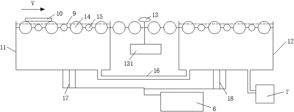
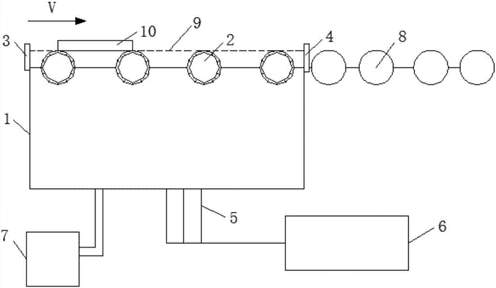
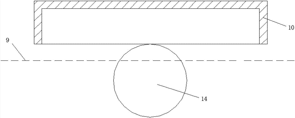
[0036] see Figure 1-5 , the present invention provides a technical solution:

[0037] A SCHMID etching tank that can reduce acid consumption, as shown in the attached figure 2 As shown, including the tank body 1, a number of spiral back throwing rollers 2 are horizontally arranged at the opening of the tank body 1, and the number of the spiral back throwing rollers 2 depends on the length of the tank body 1. Adjust the spiral back throwing rollers 2 to keep...


PUM


Abstract

The invention discloses an SCHMID etching tank capable of reducing acid consumption. The SCHMID etching tank comprises a tank body, a plurality of spiral back polishing rollers are horizontally arranged at the opening of the tank body, and a front baffle and a back baffle are movably arranged on outer side walls of two ends of the tank body; and a manual valve is arranged on a lower end of the tank body, the manual valve is connected with a TANK, and the tank body is further connected with a liquid level test box. The invention further discloses a use method of the SCHMID etching tank capable of reducing the acid consumption. The method comprises the following steps: S1: adjusting the heights of the front baffle and the back baffle; S2: setting the height of the liquid level through the liquid level test box; S3: opening the TANK, and injecting liquid in the tank body through the manual valve; and S4: adding a silicon wafer to the tank body from the front baffle for etching. By adoption of the SCHMID etching tank disclosed by the invention, the consumption of nitric acid is reduced by 80%, the consumption of hydrofluoric acid is reduced by 65%, the power consumption cost is greatly reduced, and due to the reduction of the power consumption, no exhaust pipe needs to be arranged; and moreover, the utilization rate of an SCHMID machine is greatly reduced, the equipment maintenance cost is reduced, and the SCHMID etching tank is very effective.

Description

technical field [0001] The invention relates to the technical field of silicon wafer etching, in particular to a SCHMID etching tank capable of reducing acid consumption and a method for using the same. Background technique [0002] In the process of silicon wafer forming PN junction by phosphorus diffusion, although back-to-back diffusion is adopted, phosphorus will inevitably be diffused on the edge of silicon wafer. The photogenerated electrons collected on the front side of the PN junction will flow to the back side of the PN junction along the diffused phosphorus area along the edge to cause a short circuit, so we need to etch the edge of the diffused silicon wafer. The existing SCHMID machine uses the mixed liquid of HNO3 and HF to etch the lower surface and edge of the diffused silicon wafer to remove the N-type silicon at the edge, so that the upper and lower surfaces of the silicon wafer are insulated from each other. [0003] As attached to the manual figure 1 As...

Claims


Application Information

Patent Timeline
Patent Type & Authority Applications(China)
IPC IPC(8): H01L21/67H01L21/306C23F1/08C23F1/24
CPCH01L21/30604H01L21/67086C23F1/08C23F1/30
Inventor 周守亮苏世杰顾峰
Owner TONGWEI SOLAR (ANHUI) CO LTD
Why Eureka
Try Eureka