Circular-polarized back-cavity waveguide slot array antenna realized near-field coupling polarizer

A waveguide slot and near-field coupling technology, which is applied in the field of communication, can solve problems such as difficult installation and increased antenna loss, and achieve the effects of suppressing surface waves, improving performance, and simple structure

Pending Publication Date: 2017-09-22
FUDAN UNIV
View PDF5 Cites 20 Cited by
  • Summary
  • Abstract
  • Description
  • Claims
  • Application Information

AI Technical Summary

Problems solved by technology

[0004] The traditional polarizer is generally placed at a distance of 1 / 5 from the gap and supported by foam material. The use of foam material will increase the loss of the antenna and is not easy to install

Method used


Image

  • Circular-polarized back-cavity waveguide slot array antenna realized near-field coupling polarizer
  • Circular-polarized back-cavity waveguide slot array antenna realized near-field coupling polarizer
  • Circular-polarized back-cavity waveguide slot array antenna realized near-field coupling polarizer

Examples


Embodiment Construction

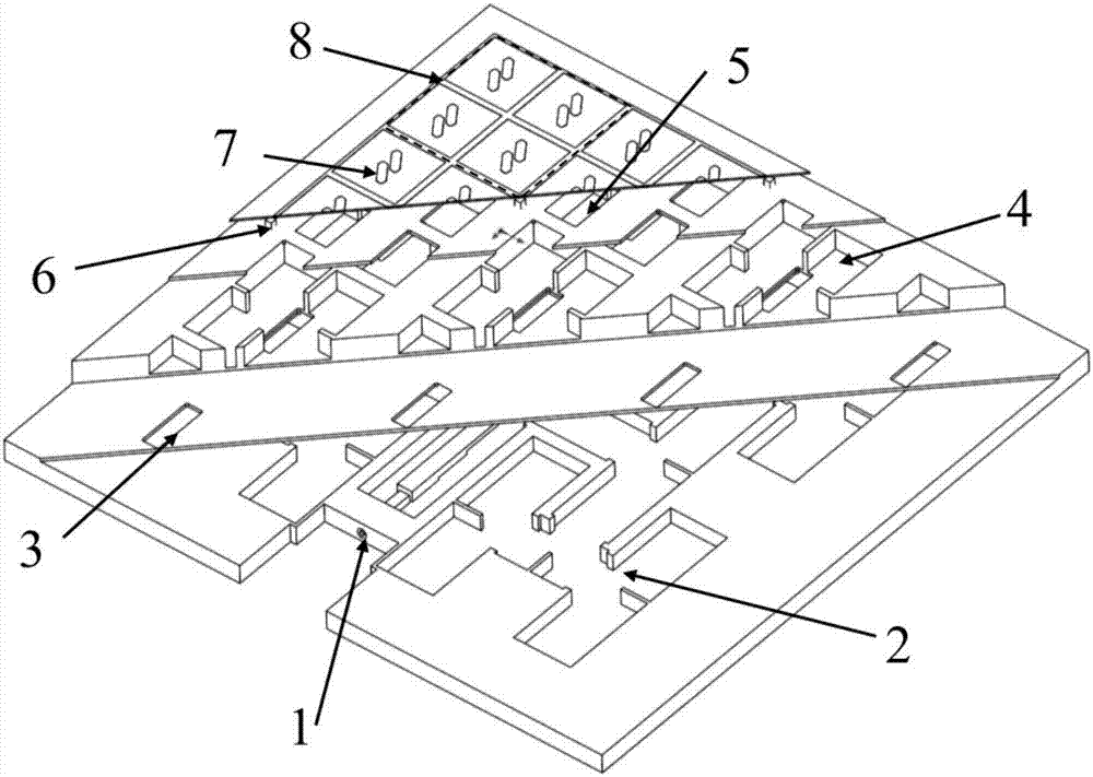
[0028] like figure 1 Shown is a schematic diagram of the structure of a circularly polarized cavity-backed slot array. The antenna array consists of a coaxial interface 1, a waveguide feed network 2, a coupling slot 3, a resonant cavity 4, a radiation slot 5, a metal support column 6 and a corner-cut circular polarization Device 7 consists of seven parts. The metal structure at the lower end is processed by a CNC machine tool, and the corner-cut circular polarizer at the upper end is processed by a traditional PCB process.

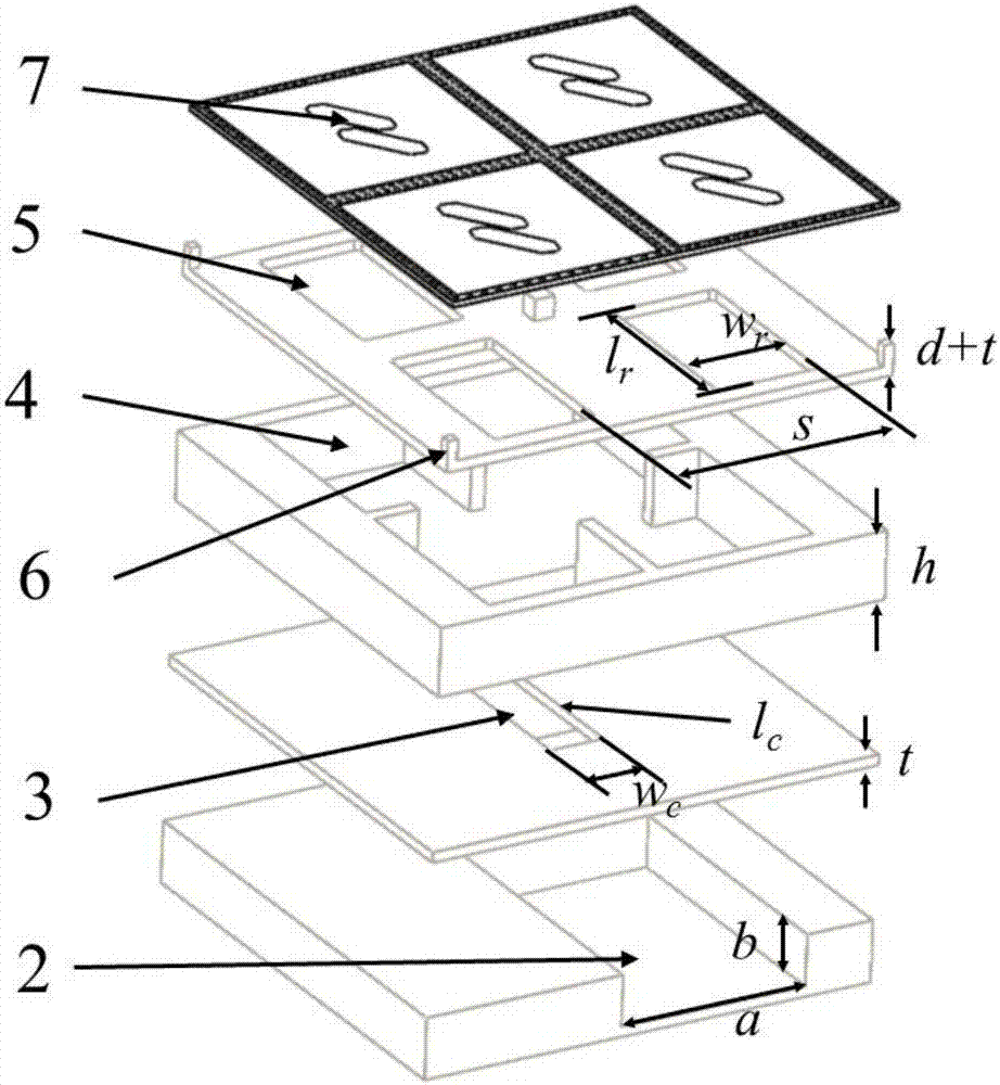
[0029] like figure 2 The schematic diagram of the explosion of the 2×2 sub-array is shown. The metal structure at the lower end is composed of four layers, the coaxial interface and the waveguide feed network are one layer, the coupling gap is one layer, the resonant cavity is one layer, the radiation gap and the metal support The column is one layer. During processing, the four-layer structure is processed separately with a CNC machine tool, and then ...


PUM


Abstract

The invention belongs to the technical field of the communication, specifically a Circular-polarized back-cavity waveguide slot array antenna realized near-field coupling polarizer. The antenna array is composed of two parts: the lower end is the linear-polarized back-cavity waveguide slot array with high gain and low section, and the upper end is a biparasitic corner-truncated patch polarizer; the corner-truncated patch polarizer is composed of two corner-truncated parasitic patches, each two patches are isolated by using a metal belt electrically connected with a metal through hole; the linear-polarized back-cavity waveguide slot array is composed of a coaxial interface, a feed waveguide network, a coupling slot, a resonant cavity, a radiation slot and a support column; a periodical metal prop integrally machined with lower end antenna is supported between the polarizer and the antenna array plane; the assembling is convenient, the structure is compact, the additional loss material is unnecessary to import, and the features of high gain and low loss of the original waveguide back-cavity antenna are maximally reserved; furthermore, the surface wave between a polarizer medium substrate and an air contact surface can be commonly inhibited, and the performance of the antenna is effectively improved.

Description

technical field [0001] The invention belongs to the technical field of communication, and in particular relates to a circularly polarized fixed beam antenna array, in particular to a circularly polarized cavity-backed waveguide slot array converted into a circularly polarized array by a corner-cut patch circular polarizer. Background technique [0002] Circularly polarized antennas are widely used in the field of wireless communication because of their small polarization deflection loss and polarization reversal after reflection, which can effectively suppress the interference caused by multipath effects. With the rapid development of wireless communication, various circularly polarized antennas have been designed, such as helical antennas, crossed dipole antennas, and patch antennas. The patch antenna has received extensive attention because of its simple processing, compact structure, and cross-section characteristics, and various forms of circularly polarized patch antenn...

Claims


Application Information

Patent Timeline
Patent Type & Authority Applications(China)
IPC IPC(8): H01Q21/00H01Q21/24H01Q15/24H01Q13/10H01Q1/36H01Q1/50
CPCH01Q1/36H01Q1/50H01Q13/10H01Q15/244H01Q21/0006H01Q21/245
Inventor 尹卫爽关放刘晓晗资剑
Owner FUDAN UNIV
Why Eureka
Try Eureka