3D print head

A 3D printing and nozzle technology, which is applied in the field of 3D printing nozzles, can solve the problems of coarse grains, cracks, and lack of fusion, and achieve the effects of refining grains, improving printing quality, and improving bonding strength.

Inactive Publication Date: 2017-09-26
WUHAN UNIV OF TECH
View PDF6 Cites 23 Cited by
  • Summary
  • Abstract
  • Description
  • Claims
  • Application Information

AI Technical Summary

Problems solved by technology

[0003] However, industrial applications have higher requirements on the quality of 3D printed metal parts. 3D printed metal components using lasers and electron beams as heat sources are surfacing layer by layer after melting metal powder or metal wire according to the set path, and finally form the target. The essence of parts is welding, so 3D printed metal parts must have welding defects such as pores, cracks, inclusions, and lack of fusion. At the same time, metal parts have coarse grains and weak bonding between layers. Disadvantages such as low strength
At the same time, the traditional 3D printing process of metal materials cannot be carried out in the atmospheric environment. During the printing process, the molten metal is easily oxidized by oxygen in the air, and a very thin oxide film is quickly formed on the metal surface to hinder the connection between the upper metal and the lower metal. The effective connection between them must be carried out in a vacuum environment or a protective atmosphere environment, which greatly increases the cost of the equipment and the difficulty of operation

Method used


Image

  • 3D print head
  • 3D print head
  • 3D print head

Examples


Embodiment 1

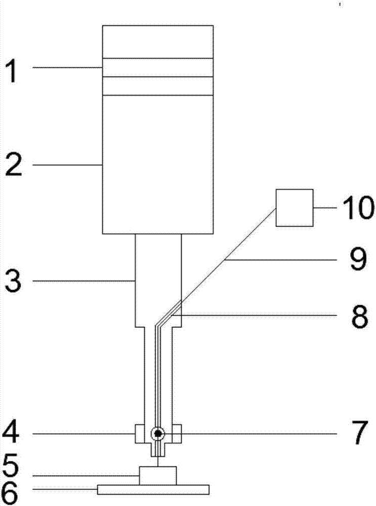
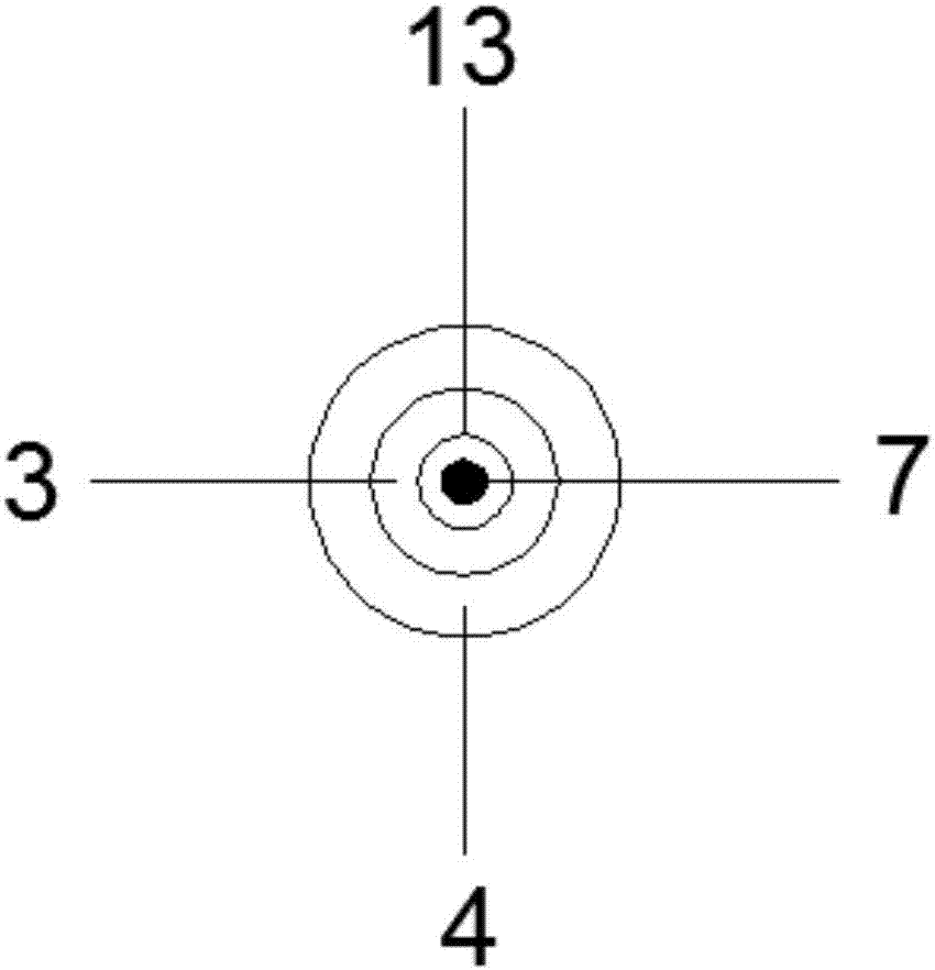
[0021] Such as figure 1 As shown, this embodiment provides a 3D printing nozzle, including an ultrasonic transducer 1, an ultrasonic horn 2, and an ultrasonic welding rod 3. The ultrasonic transducer 1 and the ultrasonic horn 2 are connected by bolts. The ultrasonic welding rod 3 is connected with the ultrasonic horn 2, and the ultrasonic welding rod 3 is provided with a through hole 8 for conveying printing materials. The upper end of the through hole 8 is an upward bending hole, and the entrance of the upper end is located One side of the ultrasonic welding rod 3; the lower end of the through hole extends to the end of the ultrasonic welding rod 3, and a melting device for heating the printing material to a molten state is also arranged. Such as figure 2 As shown, in this embodiment, the melting device is a heating device 4, and the heating device 4 is an annular resistance heater, which is installed at the lower end of the ultrasonic welding rod 3, and a nugget cavity is ...

Embodiment 2

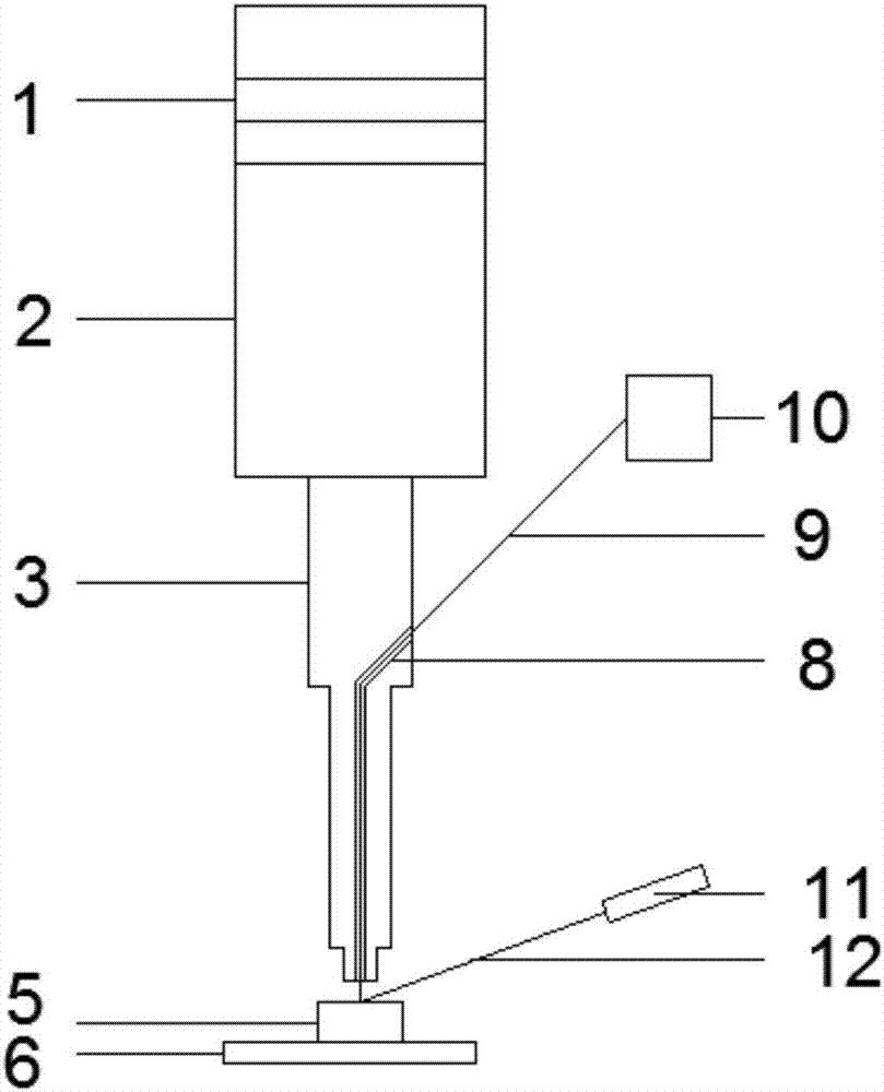
[0026] Such as image 3 As shown, the structure of this embodiment is basically the same as that of Embodiment 1, the difference lies in: the difference of the melting device, the melting device in this embodiment is a laser heating emitter 11, and the heating focus of the laser 12 emitted by it is between the printing material and the The location of the workpiece contact.

[0027] Specific examples:

[0028] The printing material 9 is an ABS filament material with a diameter of 2mm. In the atmospheric environment, the material conveying device 10 is a wire feeder, and the diameter of the through hole 8 is 2.2mm. Insert one end of the ABS filament material into the material conveying device 10, and the material conveys The device 10 feeds the ABS wire into the through hole 8 of the ultrasonic variable welding rod 3, and the printing material reaches the bottom of the through hole and protrudes out. Under the irradiation of the laser 12, it forms a molten state and contacts t...


PUM


Abstract

The invention discloses a 3D print head. The 3D print head is characterized by comprising an ultrasonic transducer, an ultrasonic amplitude transformer and an ultrasonic welding rod. The ultrasonic transducer is connected with the ultrasonic amplitude transformer, the ultrasonic welding rod is connected with the ultrasonic amplitude transformer, the ultrasonic welding rod is provided with a through hole which is used for conveying a printing material, the through hole extends to the end portion of the ultrasonic welding rod, and a fusing device which is used for heating the printing material into a molten state is also arranged. According to the 3D print head, the ultrasonic transducer and the ultrasonic amplitude transformer generate and amplify ultrasonic vibration, the bottom of the ultrasonic welding rod makes direct contact with the molten material, the ultrasonic vibration is transmitted into the molten material, when the metal printing material is printed in a vacuum or protective atmosphere, the molten metal makes contact with a printed workpiece, an upper metal layer is connected with a lower metal layer, under the ultrasonic vibration environment, structure grains are refined, pores, cracks, incomplete fusion and other defects are reduced, the structure performance is improved, the combination strength between the layers is improved, and the printing quality is further improved.

Description

technical field [0001] The invention relates to a printing nozzle, in particular to a 3D printing nozzle. Background technique [0002] 3D printing is a kind of rapid prototyping technology. It is a technology based on digital model files and using bondable materials such as powdered metal or plastic to construct objects by layer-by-layer printing. 3D printing technology is widely used in industry, medical and other fields. At present, large-scale main load-bearing key components of titanium alloy have been manufactured by 3D printing technology. In medicine, 3D printing technology has printed capillaries, spine, etc. and has been clinically obtained. application. Commonly used 3D printing technologies include 3D printing of plastics and 3D printing of metal materials. The working principle of Fused Deposition Modeling (FDM) technology is that thermoplastic filamentary materials are sent from the wire feeding mechanism to the thermal nozzle, and heated and melted into a sem...

Claims


Application Information

Patent Timeline
Patent Type & Authority Applications(China)
IPC IPC(8): B22F3/105B29C64/307B29C64/118B33Y30/00
CPCB22F3/003B33Y30/00B22F10/00B22F12/10B22F10/22B22F10/25B22F12/53Y02P10/25
Inventor 肖勇毛永灵李姗宋志鹏傅华强
Owner WUHAN UNIV OF TECH
Why Eureka
Try Eureka