Treatment method of oil-based drilling cuttings and oily sludge

A technology of oil-based drilling cuttings and treatment method, which is applied in sludge treatment, water/sludge/sewage treatment, dehydration/drying/concentrated sludge treatment, etc., can solve the problems of high treatment cost and expensive extraction agent, etc. Achieve a wide range of applications, high recycling efficiency, and reduce environmental pollution.

Inactive Publication Date: 2017-09-26
巴州华源泰克油田技术有限公司
View PDF0 Cites 19 Cited by
  • Summary
  • Abstract
  • Description
  • Claims
  • Application Information

AI Technical Summary

Problems solved by technology

The advantage is high efficiency, thorough treatment, and most of the petroleum substances are extracted and recovered; the disadvantage is that the extraction agent is expensive, there is some loss in the process, and the treatment cost is high

Method used


Image

  • Treatment method of oil-based drilling cuttings and oily sludge
  • Treatment method of oil-based drilling cuttings and oily sludge
  • Treatment method of oil-based drilling cuttings and oily sludge

Examples


Embodiment 1

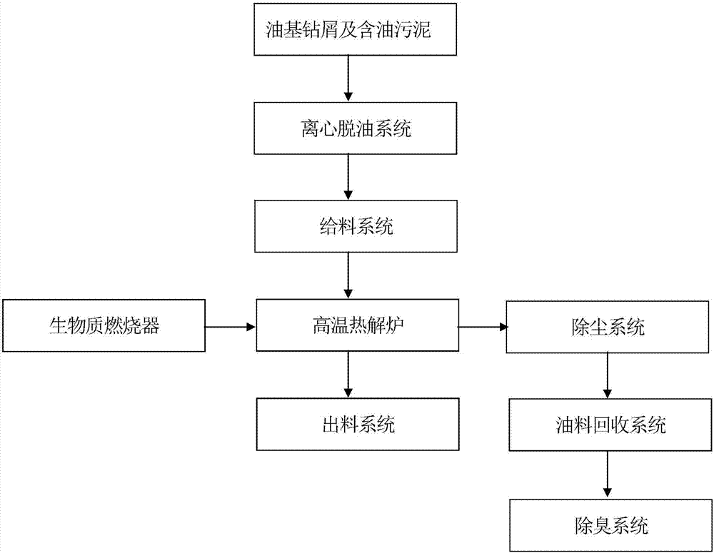
[0034] in figure 1 In the present invention, the method for treating oil-based drill cuttings and oily sludge consists of the following steps:

[0035] 1). Transport oil-based drilling cuttings and oily sludge to the centrifugal deoiling system for deoiling; the drilling cuttings and oily sludge processed by the centrifugal deoiling system enter the high-temperature pyrolysis furnace from the feeding system, and more than 80% of the Oil-based mud is recycled and reused; the centrifugal de-oiling system described in this embodiment is a centrifugal de-oiling machine, and the feeding method of the feeding system adopts the circulating exhaust feeding method, which can ensure the air lock effect and ensure the continuity of feeding. Uniformity.

[0036] 2) The processed oil-bearing drilling cuttings are pyrolyzed and vaporized in the high-temperature pyrolysis furnace; the biomass burner generates high-temperature hot air to supply the heat of the high-temperature pyrolysis furnace; ...

Embodiment 2

[0044] In embodiment 1, step 2) of this embodiment, the processed oil-bearing drilling cuttings are pyrolyzed and vaporized in the high-temperature pyrolysis furnace; the biomass burner generates high-temperature hot air to supply the heat of the high-temperature pyrolysis furnace; the drilling cuttings are in The conditions for pyrolysis and vaporization in the high-temperature pyrolysis furnace include: a temperature of 260°C, an oxygen-free negative pressure value of 7MPa, and a time of 2h. The rest of the steps are exactly the same as in Example 1.

Embodiment 3

[0046] In embodiment 1, step 2) of this embodiment, the processed oil-bearing drilling cuttings are pyrolyzed and vaporized in the high-temperature pyrolysis furnace; the biomass burner generates high-temperature hot air to supply the heat of the high-temperature pyrolysis furnace; the drilling cuttings are in The conditions for pyrolysis and vaporization in the high-temperature pyrolysis furnace include: a temperature of 1150°C, an oxygen-free negative pressure value of 35MPa, and a time of 48h. The rest of the steps are exactly the same as in Example 1.

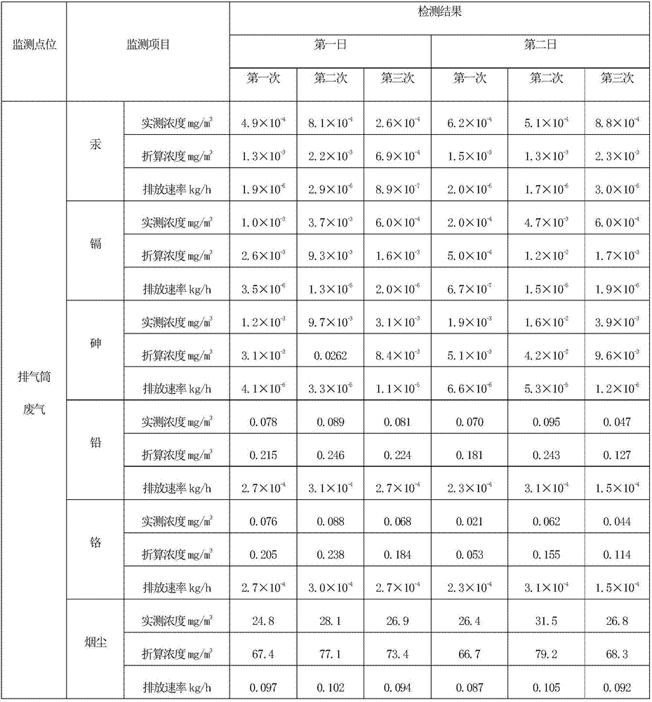
[0047] Tables 1, 2, and 3 are the data of each monitoring item of the exhaust gas from the exhaust tube treated by the treatment method of the present invention, and Tables 4-8 are the data of each detection item of the mud and mud cake treated by the treatment method of the present invention.

[0048] Table 1 Exhaust gas from exhaust pipe

[0049]

[0050]

[0051] Table 2 Exhaust gas from exhaust pipe

[0052]

[0053] Table 3 E...


PUM


Abstract

The invention discloses a treatment method of oil-based drilling cuttings and oily sludge. The treatment method comprises the following steps: 1) conveying the oil-based drilling cuttings and the oily sludge into a centrifugal oil-removing system to remove oil, and feeding the drilling cuttings and the oily sludge treated by the centrifugal oil-removing system into a high-temperature pyrolysis furnace through a feeding system to recycle 80 percent or more of oil-based sludge; 2) pyrolyzing and vaporizing the treated oily drilling cuttings in the high-temperature pyrolysis furnace, supplying high-temperature hot air generated by a biomass burner into the high-temperature pyrolysis furnace to generate heat, discharging drilling cuttings treated with the high-temperature pyrolysis furnace through a discharging system, and introducing waste gas into a de-dusting system and an oil recycling system for further treatment; 3) introducing the waste gas treated with the de-dusting system and the oil recycling system into a deodorizing system for final de-dusting and deodorizing treatment. The treatment method has a wide application range, and can be popularized to treatment of various oily sludge and oil-based drilling cuttings.

Description

Technical field [0001] The invention belongs to the technical field of treatment devices or methods for water, wastewater, sewage or sludge, and specifically relates to a treatment method for oil-based drill cuttings and oily sludge. Background technique [0002] With the development of drilling technologies for high temperature and high pressure deep wells, highly inclined directional wells, horizontal wells and various complex formations, commonly used water-based drilling fluids can no longer fully meet the needs of high-tech drilling. Oil-based drilling fluids are due to their excellent inhibition. And temperature resistance, it has more obvious advantages in drilling complex wells, especially in drilling high temperature deep wells and water sensitive formations. There are more and more waste oil-based mud from drilling. It is a complex multi-phase system containing mineral oil, phenolic compounds and heavy metals, and its leaching fluid is highly toxic. Oil field drilling ...

Claims


Application Information

Patent Timeline
Patent Type & Authority Applications(China)
IPC IPC(8): C02F11/12C02F11/10B01D50/00B01D53/00B01D53/02C02F103/10
CPCB01D53/00B01D53/02C02F11/10C02F11/127C02F2103/10B01D50/40B01D50/60Y02W10/40
Inventor 陈俊敏禹林
Owner 巴州华源泰克油田技术有限公司
Why Eureka
Try Eureka