Underwater array scanning laser imaging device and method

A scanning laser and imaging device technology, applied in image communication, TV, color TV components, etc., can solve the problems of underwater long-distance and large field of view optical imaging, and achieve high engineering realizability and reduce power consumption , the effect of improving the detection performance

Active Publication Date: 2017-10-10
中国人民解放军92232部队 +2
View PDF13 Cites 11 Cited by
  • Summary
  • Abstract
  • Description
  • Claims
  • Application Information

AI Technical Summary

Problems solved by technology

[0006] The purpose of the present invention is to overcome the above-mentioned defects existing in the current underwater scanning technology, and propose an underwater array scanning laser imaging device, which can solve the difficult problem of underwater long-distance and large-field optical imaging, and can realize underwater large-scale imaging. Field of View 3D Imaging

Method used


Image

  • Underwater array scanning laser imaging device and method
  • Underwater array scanning laser imaging device and method
  • Underwater array scanning laser imaging device and method

Examples


Embodiment 1

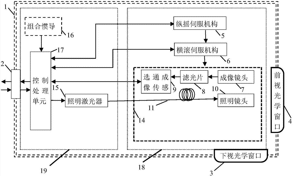
[0057] Such as Figure 1a Shown, a kind of underwater array scanning laser imaging device, said device comprises: carrier 1, electrical module 19 and imaging module 18;

[0058] The carrier 1 is the shell of the whole device, which meets the pressure-resistant requirements of underwater work, and can perform information exchange and power supply with the unmanned submersible 25 through the plug 2 connection cable; the overall appearance of the carrier 1 is cylindrical, and the head The head is spherical, the head has a forward-looking optical window 4, and the abdomen of the carrier has a downward-looking optical window 3;

[0059] The electrical module 19 includes an illumination laser 15, a combined inertial navigation 16 and a control processing unit 17; Figure 2a As shown, the components of the electrical module 19 are fixed on both sides of the circular mounting plate 22, and are fixed to the shell of the carrier 1 through the mounting plate 22;

[0060] The imaging mod...

Embodiment 2

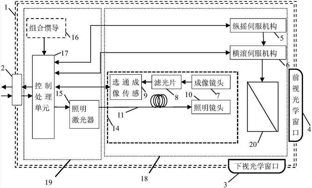
[0074] The schematic diagram of the device is shown in Figure 1b As shown, it is similar to the device in Embodiment 1, the difference is that the imaging module 18 also includes a reflector 20, which is loaded on the roll servo mechanism 6 and arranged in front of the optical imaging module 14 to emit the illumination lens 10 The laser light is reflected to the specified direction, and the laser light reflected from the target is reflected to the imaging lens 7, that is, the optical axis of the optical imaging module is pointed to the specified direction.

Embodiment 3

[0076] The schematic diagram of the device is shown in Figure 1c As shown, similar to Embodiment 1, the difference is that the imaging module 18 also includes a search guidance and ranging unit, which is used to measure the distance of the target and feed back the distance information to the control processing unit 17; The search guide and distance measuring unit includes a receiving lens 12 and a photodetector 13, and the illumination laser 15 provides nanosecond-level laser pulses for the search guide and distance measuring unit, and performs distance measurement through time delay information;

[0077] The control processing unit 17 also includes a distance measurement processing subunit, which is used to receive the target distance information from the search guide and distance measurement unit, and convert the distance information into delay information to generate control gate imaging sensor 9 and illumination laser 15 working timings to achieve underwater range-gated i...


PUM


Abstract

The invention provides an underwater array scanning laser imaging device comprising a carrier (1), an electrical module (19) and an imaging module (18), wherein the carrier (1) is the shell of the whole device; the electrical module (19) comprises a lighting laser (15), a combined inertial navigation unit (16) and a control processing unit (17); components of the electrical module (19) are fixed on two sides of an installation plate (22), and fixed with the carrier (1) via the installation plate (22); the imaging module (18) comprises a pitching servo mechanism (5), a rolling servo mechanism (6) and an optical imaging module (14); the optical imaging module (14) comprises an imaging lens (7), a filtering plate (8), a hating imaging sensor (9) and a lighting lens (10); laser emitted by the lighting laser (15) can be transmitted to the lighting lens (10) via an energy transmission optical fiber (11). The device provided by the invention has the characteristics of being miniature, and capable of achieving array scanning under water.

Description

technical field [0001] The invention relates to the technical field of underwater imaging, in particular to an underwater array scanning laser imaging device and method. Background technique [0002] High-resolution, large-field underwater imaging is of great civil and military significance in the fields of underwater topography and geomorphology mapping, maintenance and survey of submarine oil pipelines and optical cables, search for underwater wreckage of ships and aircraft, and mine detection. [0003] Sonar imaging uses sound waves to judge the existence, location and type of objects in the ocean, and has the advantages of wide field of view and large ranging range. However, due to the complexity of the underwater acoustic channel, which is greatly affected by the environment (such as the ocean thermocline), compared with the optical image, the resolution of the underwater acoustic image is low, the noise is serious, the image quality is not high, and there is a blind sp...

Claims


Application Information

Patent Timeline
Patent Type & Authority Applications(China)
IPC IPC(8): H04N5/225H04N5/232
CPCH04N23/56H04N23/54H04N23/50H04N23/55H04N23/80
Inventor 王全喜王新伟肖昌美李庶中李广良周燕赵江张鹏李越强姚林海柳秋兴
Owner 中国人民解放军92232部队
Why Eureka
Try Eureka