Digital PCR chip signal reading method

A chip and signal technology, applied in the field of digital PCR chip signal reading, can solve the problem of low detection accuracy and achieve the effect of improving detection accuracy

Inactive Publication Date: 2017-10-17
澎湃生物科技(苏州)有限公司
View PDF5 Cites 12 Cited by
  • Summary
  • Abstract
  • Description
  • Claims
  • Application Information

AI Technical Summary

Problems solved by technology

[0006] In view of the above-mentioned shortcomings of the prior art, the purpose of the present invention is to provide a digital PCR chip signal reading method, which is used to solve the problem of low detection accuracy caused by the limitation of liquid volume in digital PCR detection in the prior art

Method used


Image

  • Digital PCR chip signal reading method
  • Digital PCR chip signal reading method
  • Digital PCR chip signal reading method

Examples


Embodiment 1

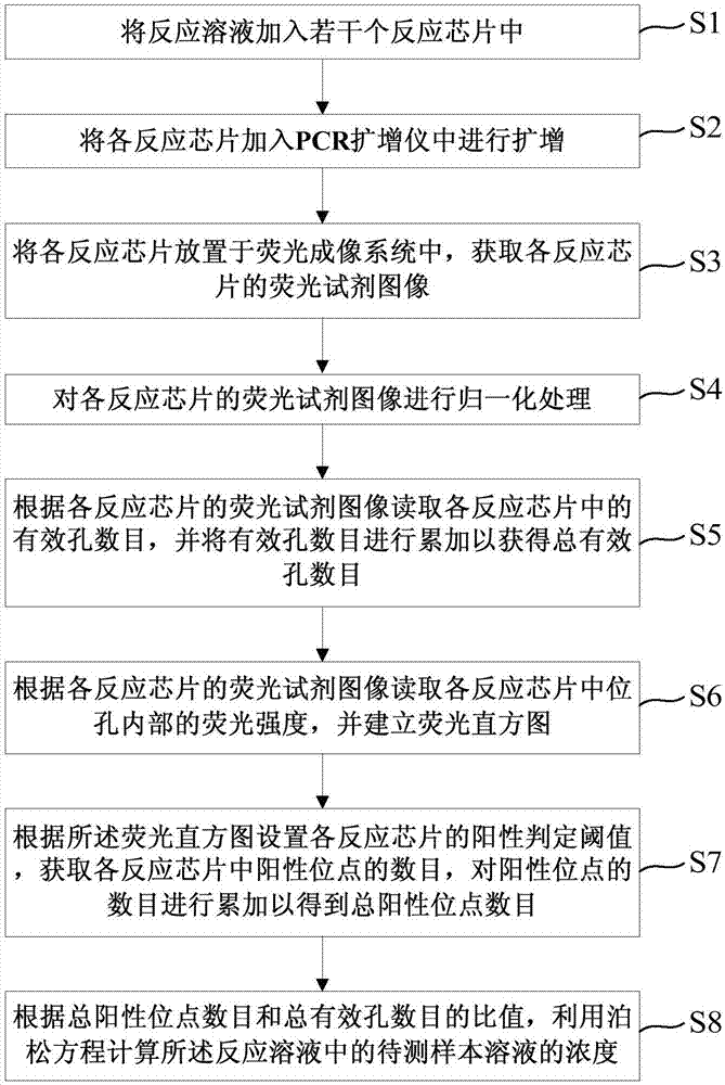
[0072] Such as figure 1 As shown, the present embodiment provides a digital PCR chip signal reading method, and the digital PCR chip signal reading method specifically includes the following steps:

[0073] Step S1: adding the reaction solution into several reaction chips, oil-sealing each coated reaction chip with mineral oil, and then sealing each reaction chip with a transparent cover. The number of said reaction chips is not less than 2.

[0074] Specifically, in this embodiment, 16 digital PCR reaction chips are selected. The digital PCR chip refers to a planar micropore structure that can separate and fix the PCR reaction system. The micropore structure is a closed hole or a through hole of any geometric shape. The material of the digital PCR chip includes but is not limited to silicon base, Glass, plastic and metal, to name a few.

[0075] Specifically, in this embodiment, the reaction solution is added to each reaction chip in parallel. More specifically, configure...

Embodiment 2

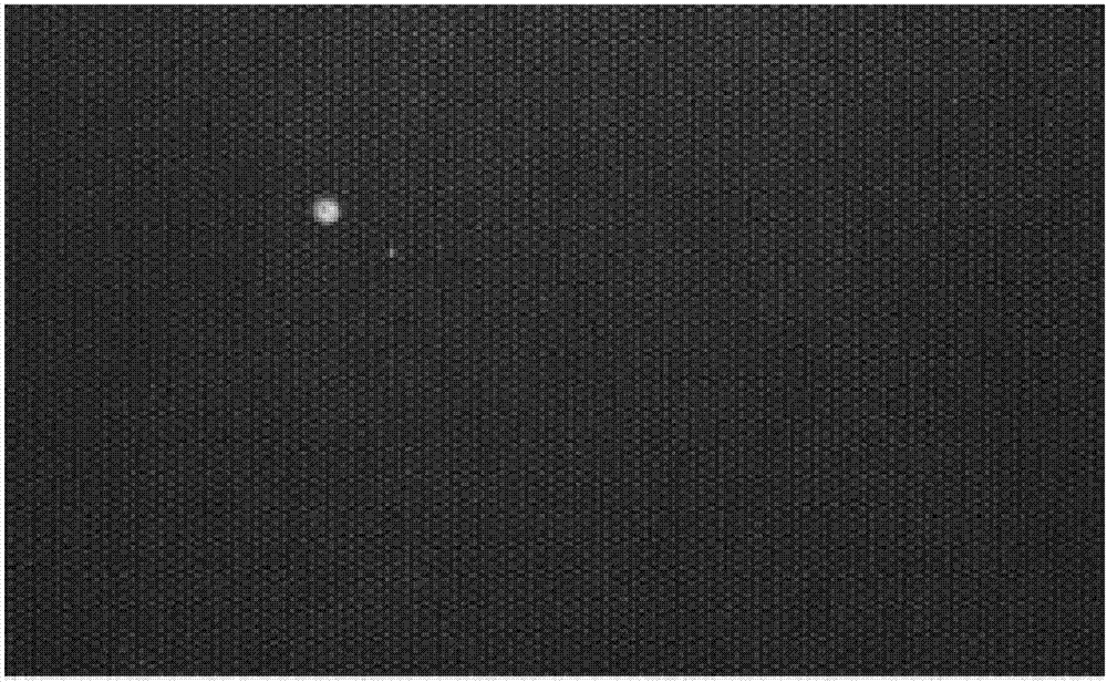
[0113] This embodiment provides a digital PCR chip signal reading method, the digital PCR chip signal reading method is basically the same as in Embodiment 1, the difference is that the FAM fluorescent reagent image is replaced with the VIC fluorescent reagent image to target different detection objects.

[0114] Specifically, in step S3, the acquired fluorescent reagent images include ROX fluorescent reagent images and VIC fluorescent reagent images. Such as Figure 4 Shown is the image of the VIC fluorescent reagent. In this embodiment, the reaction chip is irradiated with light with a wavelength of 450nm-490nm, and the image of the VIC fluorescent reagent is obtained by collecting light with a wavelength of 515nm-530nm by an image sensor.

[0115] Specifically, in step S4, normalization processing is performed on the ROX fluorescent reagent image and the VIC fluorescent reagent image, and the specific steps of the normalization processing are consistent with the first embo...

Embodiment 3

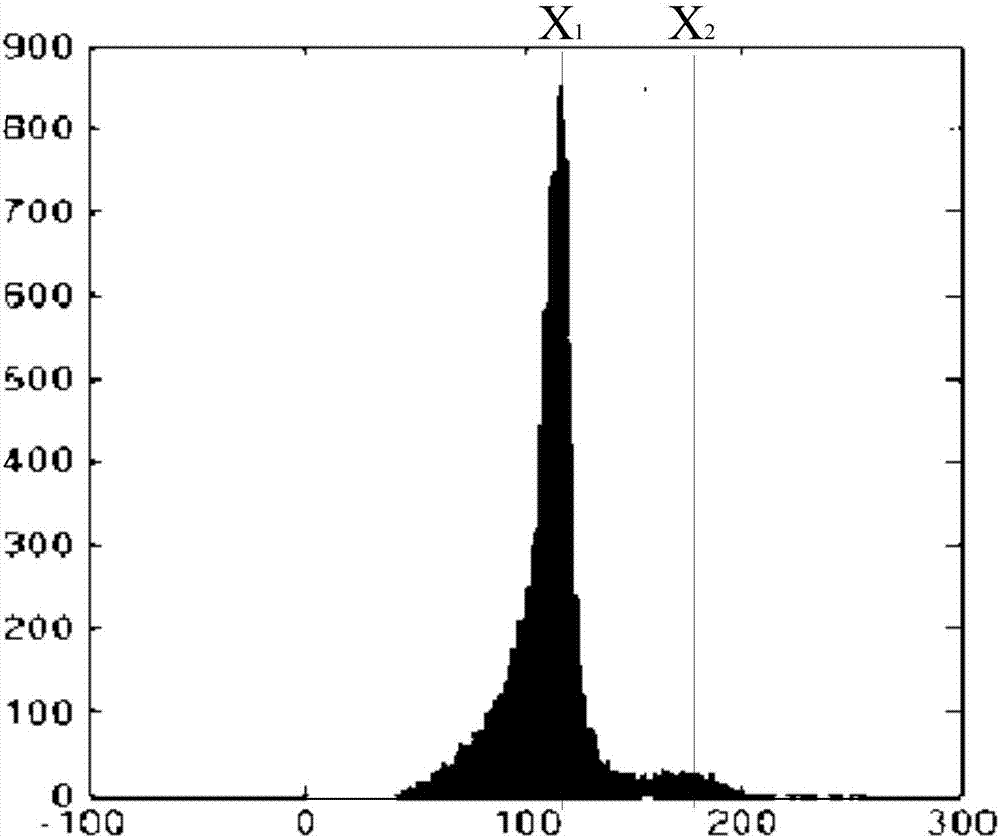
[0121] This embodiment provides a digital PCR chip signal reading method, the digital PCR chip signal reading method is basically the same as the first and second embodiments, the difference is that in step S62, the read gray value is the corresponding coordinate The gray value of the fluorescent reagent image of the pixel and the pixels around the corresponding coordinates.

[0122] Specifically, step S62: read the normalized FAM fluorescent reagent image J′ according to the center coordinates of the ROX positive well position of the corresponding reaction chip acquired in step S5 FAM Or normalized VIC fluorescence reagent image J' VIC The gray value at the corresponding coordinate and the gray value of the coordinates around the corresponding coordinate, and calculate the average value of the gray value. In this embodiment, 9 pixels around the corresponding coordinates are obtained, corresponding to 8 directions of up, down, left, right, upper left, lower left, upper right,...


PUM


Abstract

The invention provides a digital PCR chip signal reading method. The method comprises the following steps: adding a reaction solution in several reaction chips; performing amplification on each reaction chip; obtaining a fluorescence reagent image of each reaction chip; performing normalization treatment on each fluorescence reagent image; reading the effective aperture numbers in each reaction chip to obtain the total effective aperture number; reading the fluorescence intensity in apertures in each reaction chip, establishing a fluorescence histogram; according to the fluorescence histogram, setting the positive determination threshold of each reaction chip to obtain the total positive locus number, according to the ratio of the total positive locus number to the total effective aperture number, and calculating the concentration of a to-be-measured sample solution. The amplification system and the detection system is completely compatible with a current micropore chip-type digital PCR technology, several chip fluoroscopic images after amplification are obtained through a multitime imaging mode, the histogram and point diagram analysis can be carried out on the amplified chip image to obtain the digital PCR detection result with high flux, and the detection precision is increased.

Description

technical field [0001] The invention relates to the field of digital PCR biological detection, in particular to a digital PCR chip signal reading method. Background technique [0002] When performing quantitative analysis and detection of nucleic acid, nucleic acid samples are often amplified by polymerase chain reaction (Ploymerase Chain Reaction, PCR) to facilitate detection. In 1992, the real-time fluorescent quantitative PCR (Real-timePCR, qPCR) technology proposed by Higuchi et al [Polymerase chain reaction (PCR) amplification and human leukocyteantigen (HLA)-DQ alpha oligonucleotide typing on biological evidence samples: casework experience, Journal of Forensic Sciences 37(3):700-26·June 1992], has developed into one of the most commonly used quantitative analysis techniques, widely used in clinical disease diagnosis, inspection and quarantine, food safety and other fields. The analysis results of qPCR are highly dependent on the cycle threshold (Cycle threshold, Ct v...

Claims


Application Information

Patent Timeline
Patent Type & Authority Applications(China)
IPC IPC(8): C12Q1/68
CPCC12Q1/6851C12Q2531/113C12Q2563/107C12Q2563/159
Inventor 郭枫毛林芳
Owner 澎湃生物科技(苏州)有限公司
Why Eureka
Try Eureka