
UWB (ultra wide band) array antenna

An array antenna and ultra-broadband technology, which is applied in the field of structure design of ultra-broadband tightly coupled array antennas, can solve the problems of lack of bandwidth application range and limited feeding network, achieve good wave absorption effect, expand bandwidth, and enhance coupling effect. Effect

Inactive Publication Date: 2017-10-20
XIDIAN UNIV
View PDF5 Cites 22 Cited by
  • Summary
  • Abstract
  • Description
  • Claims
  • Application Information

AI Technical Summary

Problems solved by technology

[0005] Shenzhen Tianding Microwave Technology Co., Ltd., in its patent application "A Tightly Coupled Array Antenna Applied to 5G Communication System" (application number: 201610327943.4, publication number: CN 106099359A), proposed a 5G communication system The tightly-coupled array antenna, through the interdigitated dipole antenna array plate, the grid-shaped resistive frequency selective surface plate and the multi-layer structure of the ground plate and the tightly-coupled array design, the relative bandwidth can reach 149.1%. 2.8GHz~19.2GHz frequency band Active VSWR<3 application range, but the patent has the problem of lack of feed network and limited bandwidth application range

Method used


Image

  • UWB (ultra wide band) array antenna
  • UWB (ultra wide band) array antenna
  • UWB (ultra wide band) array antenna

Examples


Embodiment Construction

[0024] Below in conjunction with accompanying drawing and specific embodiment, the present invention is described in further detail:

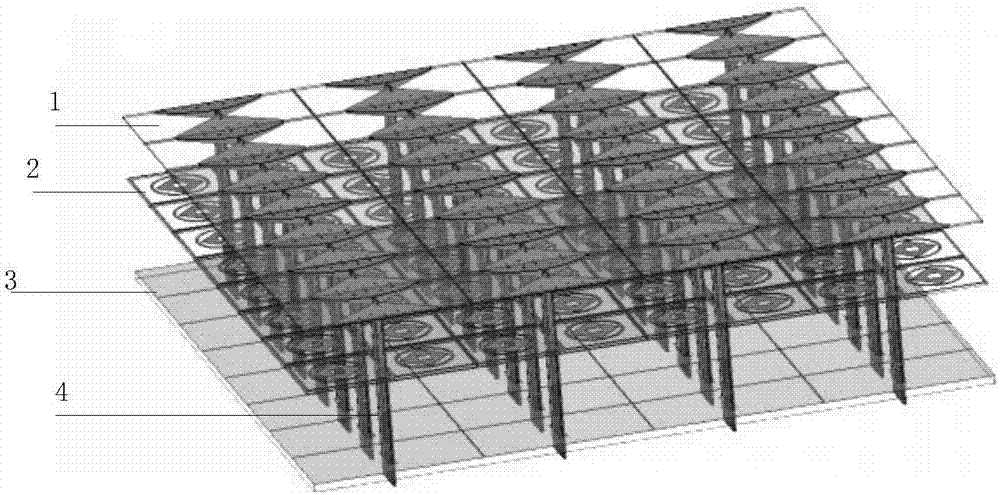
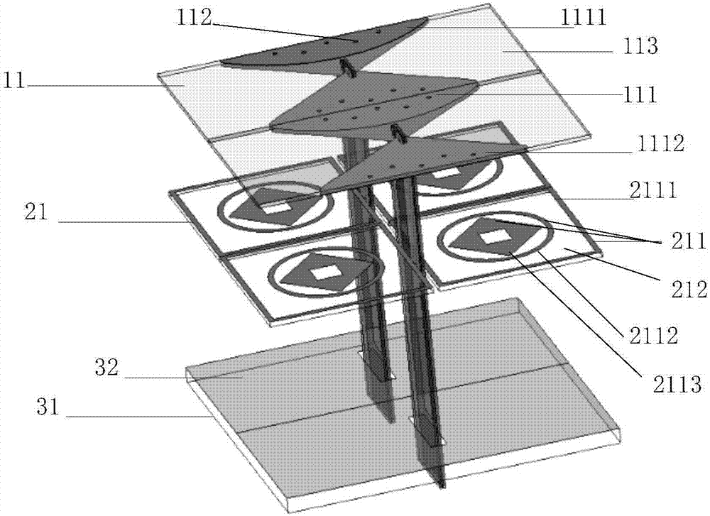
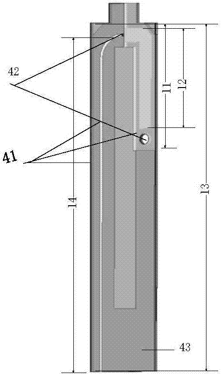
[0025] refer to figure 1 , the ultra-wideband array antenna of the present invention includes an antenna array board 1, a resistive frequency selective surface board 2, a grounding board 3 and a feed balun 4, wherein: the antenna array board 1 includes a plurality of dipole radiation period units 11, each A dipole radiation period unit 11 is located directly above the resistive frequency selective surface plate 2, parallel to the resistive frequency selective surface plate 2 and the distance between the two is 13 mm; the resistive frequency selective surface plate 2 includes a plurality of resistive frequency selective Surface unit 21, each resistive frequency selective surface unit 21 is located directly above the ground plate 3, parallel to the ground plate 3 and the distance between the two is 17mm; the upper end of the feed balun 4 and the ...


PUM


Abstract

The invention discloses a UWB (ultra wide band) array antenna, and mainly solves a problem that the bandwidth of a conventional array antenna is limited by the bandwidth of an antenna unit. The antenna comprises a dipole antenna array plate (1), a resistor-type frequency selection surface plate (2), a grounding plate (3) and a feed Balun (4). The antenna array plate consists of a plurality of dipole radiation periodic units, and each dipole radiation periodic unit comprises a dipole arm (111), a metal via hole (112) and a dielectric plate (113), wherein the dipole arms (111) are arranged on the upper and lower surfaces of the antenna array plate in a cross manner. The resistor-type frequency selection surface unit consists of a resistor paster and a dielectric plate, wherein the resistor paster consists of a square ring paster, a circular ring, and a rhombus paster. Through the close coupling between units, the reflection coefficient of the antenna at the band from 0.63GHz to 4.6GHz is less than or equal to -6dB, and the array bandwidth can be increased to 7.3 frequency multiplications. The antenna is used for FOPEN radars and through-the-wall imaging radars.

Description

technical field [0001] The invention belongs to the technical field of antennas, and in particular relates to the structural design of an ultra-wideband tightly coupled array antenna, which can be used in modern communication FOPEN radars and through-wall imaging radar systems. technical background [0002] Broadband array antennas are widely used in radar and communication. Modern phased array antennas use electronic systems to control the feed amplitude and phase of each unit in the antenna array, and use the main lobe beam of the array to scan. When the array antenna has broadband characteristics and can perform wide-angle scanning at the same time, it constitutes a broadband phased array antenna. [0003] Phased array technology first appeared in the 1930s and was mainly used in the field of military radar. The traditional broadband phased array antenna design needs to independently design a broadband antenna element first, then place it in the array and try to make it ...

Claims


Application Information

Patent Timeline
Patent Type & Authority Applications(China)
IPC IPC(8): H01Q1/38H01Q1/50H01Q9/04H01Q9/28H01Q15/00H01Q17/00H01Q21/00H01Q21/06H01P5/10
CPCH01P5/10H01Q1/38H01Q1/50H01Q9/0407H01Q9/285H01Q15/0026H01Q17/00H01Q21/0006H01Q21/062H01Q21/065
Inventor 张帅刘爽王晓骁王兴龚书喜姜文洪涛
Owner XIDIAN UNIV
Learn More