
Environment monitoring intelligent visible light communication system and method

A technology of visible light communication and environmental monitoring, which is applied in transmission systems, short-distance systems, electromagnetic wave transmission systems, etc., can solve the problems that information data is difficult to be processed in time, real-time transmission is not realized, and the price is expensive. Reliable transmission, expensive effect

Active Publication Date: 2017-10-20
南京华睿智光信息科技研究院有限公司
View PDF12 Cites 3 Cited by
  • Summary
  • Abstract
  • Description
  • Claims
  • Application Information

AI Technical Summary

Problems solved by technology

The problem with this invention is that the movement of objects has strong randomness and uncertainty, so there is a large uncertainty in environmental measurement, and long-distance movement will allow the sensor to receive a large amount of data information, but it has not been realized and the real-time transmission of the network will make it difficult for these information data to be processed in a timely manner
It should be pointed out that both Chinese patent CN201673121U and US patent US 2013 / 0278427 A1 require special air quality detection devices or sensors, which are expensive and expensive

Method used


Image

  • Environment monitoring intelligent visible light communication system and method
  • Environment monitoring intelligent visible light communication system and method
  • Environment monitoring intelligent visible light communication system and method

Examples


Embodiment 1

[0045] Example 1: Monitoring of sewage turbidity

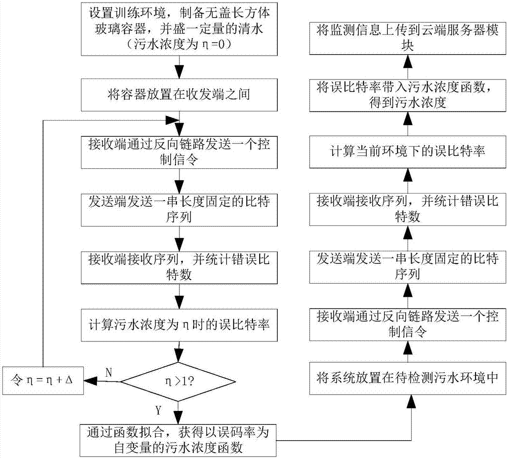
[0046] figure 2 The flow chart of monitoring the turbidity degree of sewage by the intelligent visible light communication system for environmental monitoring is given, and the process can be divided into the following steps:

[0047] 1) Set up the training environment, put a certain amount of clear water in a cuboid glass container without a cover (at this time h=0), and place the container in the middle of the transceiver. The transmission medium of the visible light signal is water.

[0048] 2) The receiving end sends a control signaling to the sending end through the reverse link.

[0049] 3) The sender sends a string of data bit sequences with a length of N.

[0050] 4) The receiving end receives the sequence and counts the number of wrong bits as N e , calculate the bit error rate BER=N e / N.

[0051] 5) Add ink, mud or other visible particles to the existing glass container to change the sewage concentration, so ...

Embodiment 2

[0056] Example 2: Monitoring of smog concentration in the atmosphere

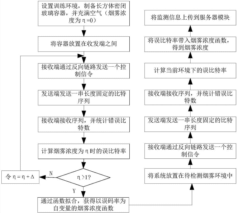
[0057] image 3 The flow chart of atmospheric smog concentration monitoring by intelligent visible light communication system for environmental monitoring is given. The process can be broken down into the following steps:

[0058] 1) Set up the training environment, fill a cuboid airtight glass container with air (at this time h=0), and place the container in the middle of the transceiver end. The transmission medium of the visible light signal is the atmosphere.

[0059] 2) The receiving end sends a control signaling to the sending end through the reverse link.

[0060] 3) The sender sends a string of data bit sequences with a length of N.

[0061] 4) The receiving end receives the sequence and counts the number of wrong bits as N e , calculate the bit error rate BER=N e / N.

[0062] 5) Change the smoke concentration in the atmosphere by filling the existing glass container with smoke, etc., so that...


PUM


Abstract

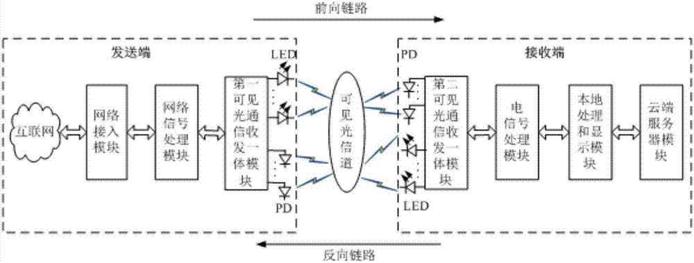
The invention discloses an environment monitoring intelligent visible light communication system and method, having dual functions of data transmission and environmental monitoring and including a network access module, a network signal processing module, first and second visible light communication transceiver modules, an electric signal processing module, a local data processing module and a cloud server module. A network signal enters the network signal processing module via the network access module and is converted into a digital signal and then enters the first visible light communication transceiver module. The signal subjected to electro-optical conversion reaches the second visible light communication transceiver module via a light-emitting diode through a visible light channel. The signal processed by the photodiode is sent to the electrical signal processing module, and a network signal is obtained and sent to a local processing and display module. Environment monitoring is realized by fitting the function of the error bit rate and the pollutant concentration and a result is uploaded to the cloud server module. The system and the method can realize reliable data transmission and monitoring of various environments and realize intelligent transmission of visible light communication.

Description

technical field [0001] The present invention relates to a visible light communication system, in particular to a visible light communication system with dual functions of data transmission and environment monitoring. Background technique [0002] Visible Light Communications (Visible Light Communications, VLC) is a new, short-distance, high-speed wireless communication technology developed on technologies such as Light Emitting Diode (LED). It uses LED as the light source, the atmosphere or water as the transmission medium, and transmits information by sending out visible light signals that are imperceptible to the naked eye and flickering at high speed. At the receiving end, the photodiode (Photodiode, PD) is used to complete the photoelectric conversion, and then carry out The reception, regeneration, and demodulation of electrical signals are used to transmit information. Compared with traditional wireless radio frequency communication technology, VLC has the advantages ...

Claims


Application Information

Patent Timeline
Patent Type & Authority Applications(China)
IPC IPC(8): H04B10/116H04B10/25H04B10/40H04B10/50
CPCH04B10/116H04B10/2589H04B10/40H04B10/502
Inventor 王金元王永进黄鸿基周行洲项彤张雨吴浩
Owner 南京华睿智光信息科技研究院有限公司
Learn More