Flowing type adsorption apparatus for treating poisonous gases by using solid adsorbent
A solid adsorbent and poisonous gas technology, which is applied in gas treatment, membrane technology, dispersed particle separation, etc., can solve the problems of poor adsorption effect and achieve the effects of small air flow resistance, large processing gas volume and good technical effect
- Summary
- Abstract
- Description
- Claims
- Application Information
AI Technical Summary
Problems solved by technology
Method used
Image


Examples
Embodiment 1
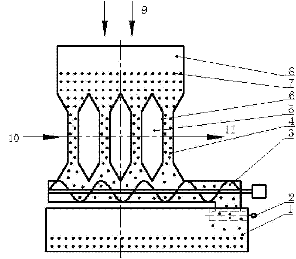
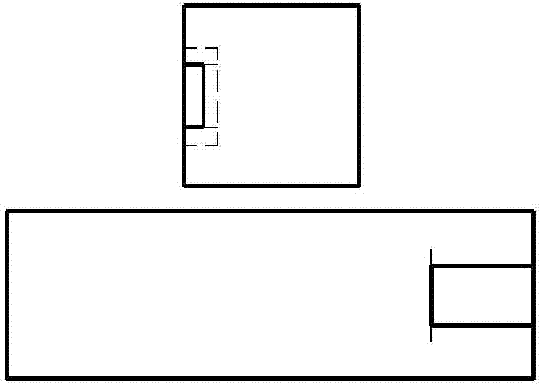
[0019] The invention provides a solid adsorbent flow type adsorption device, such as Figure 1-Figure 4 shown. The device is composed of a contact reaction chamber, a gas buffer chamber, a screw conveyor, a gas phase inlet and outlet, a feed hopper, a collection chamber, and a collection chamber baffle.
[0020] The left and right ends of the solid adsorbent flow adsorption device are respectively equipped with a gas inlet system and a gas outlet system; the solid adsorbent 7 enters the reaction chamber 4 through the feed hopper 8 under the action of its own gravity, and the reaction chamber 4 is composed of a mesh plate 6 , can block the solid adsorbent 7, so that the solid adsorbent 7 falls in the reaction chamber 4, and the screw conveyor 3 is connected with the reaction chamber 4. According to the effective action time of the solid adsorption 7, the rotation speed of the screw conveyor 3 is preset, so that The solid adsorbent that has just failed or is about to fail is tr...
Embodiment 2
[0025] According to the conditions and steps described in Example 1, the solid adsorbent is a special scavenger for hydrogen sulfide, the process conditions of the reaction chamber are 25 degrees Celsius, 0.1Mpa continuous operation, the opening rate of the mesh plate is 0.2, and toxic and harmful gases enter The ratio of the mass flow of the reaction chamber to the mass flow of the solid adsorbent is 1:50. The harmful component in the toxic and harmful gas is hydrogen sulfide, with a content of 3000ppm.
[0026] The harmful component of the treated gas is hydrogen sulfide with a content of 40ppm.
Embodiment 3
[0028] According to the conditions and steps described in Example 1, the solid adsorbent is a mixture of activated carbon / hydrophobic silica gel, the process conditions of the reaction chamber are 100 degrees Celsius, 0.5Mpa continuous operation, the opening rate of the mesh plate is 0.1, and toxic and harmful gases enter the reaction The ratio of the mass flow of the bin to the mass flow of the solid adsorbent is 1:100. The harmful component in the toxic and harmful gas is gasoline gas, the content is 10000ppm.
[0029] The harmful component of the treated gas is gasoline gas with a content of 20ppm.
PUM
 Abstract
Description
Claims
Application Information
 - R&D
- Intellectual Property
- Life Sciences
- Materials
- Tech Scout
- Unparalleled Data Quality
- Higher Quality Content
- 60% Fewer Hallucinations
Browse by: Latest US Patents, China's latest patents, Technical Efficacy Thesaurus, Application Domain, Technology Topic, Popular Technical Reports.
© 2025 PatSnap. All rights reserved.Legal|Privacy policy|Modern Slavery Act Transparency Statement|Sitemap|About US| Contact US: help@patsnap.com