Preparation method of rear-earth hexaboride field emission array

A technology of hexaboride and emission array, applied in the field of field emission array micromachining, can solve the problems of application limitation, difficulty in micromachining, unreachable radius of curvature, etc., and achieve the effect of large number density and uniform morphology

Active Publication Date: 2017-11-10
BEIJING UNIV OF TECH
View PDF3 Cites 5 Cited by
  • Summary
  • Abstract
  • Description
  • Claims
  • Application Information

AI Technical Summary

Problems solved by technology

But since REB 6 It has stable physical and chemical properties, so it is difficult to process the material by conventional micromachining methods such as particle beam etching, electron beam exposure, and chemical etching. At the same time, its hard and brittle mechanical properties lead to mechanical micromachini

Method used


Image

  • Preparation method of rear-earth hexaboride field emission array
  • Preparation method of rear-earth hexaboride field emission array
  • Preparation method of rear-earth hexaboride field emission array

Examples


Embodiment 1

[0016] 1) The bulk LaB 6 The surface is mechanically polished;

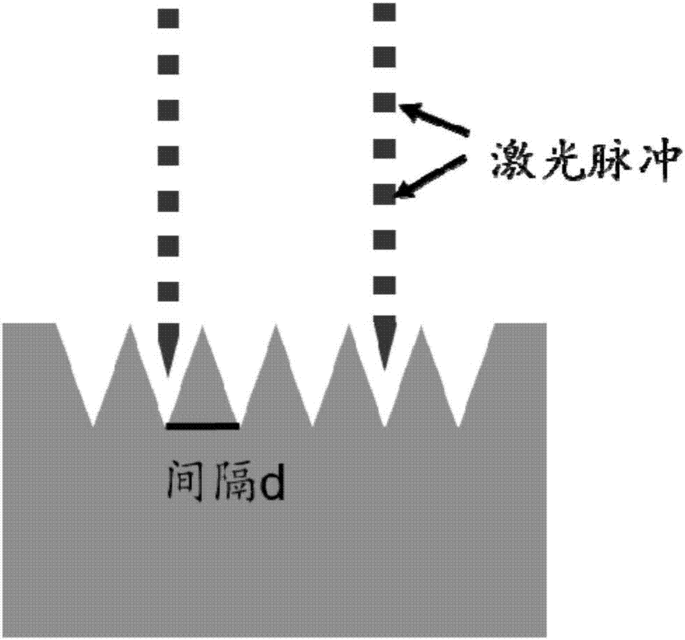
[0017] 2) Femtosecond laser micro-nano processing equipment is used, and the high-energy laser beam generated by it is used to step-polish the LaB 6 The surface is removed by laser direct writing, and the processed array density is 10,000 pieces / mm 2 ;

[0018] 3) Using femtosecond laser micro-nano processing technology to process LaB 6 When performing direct writing removal, the specific processing parameters are: under the condition of positive focus, the laser energy density is about 100J / cm 2 ;The speed of laser direct writing is 20.0mm / min; the number of equivalent pulses of laser is 50 / min; the interval of laser direct writing is 10.0μm;

Embodiment 2

[0020] 1) The bulk CeB 6 The surface is mechanically polished;

[0021] 2) Femtosecond laser micro-nano processing equipment is used, and the high-energy laser beam generated by it is used to step-polish the CeB 6 The surface is removed by laser direct writing, and the processed array density is 100,000 pieces / mm 2 ;

[0022] 3) Using femtosecond laser micro-nano processing technology to process CeB 6 When performing direct writing removal, the specific processing parameters are: under the condition of positive focus, the laser energy density is about 80J / cm 2 ;The speed of laser direct writing is 40.0mm / min; the number of equivalent pulses of laser is 100 / min; the interval of laser direct writing is 2.0μm;

Embodiment 3

[0024] 1) The bulk PrB 6 The surface is mechanically polished;

[0025] 2) Femtosecond laser micro-nano processing equipment is used, and the high-energy laser beam generated by it is used to step-polish the PrB 6 The surface is removed by laser direct writing, and the processed array density is 50,000 pieces / mm 2 ;

[0026] 3) Using femtosecond laser micro-nano processing technology to process PrB 6 When performing direct writing removal, the specific processing parameters are: under the condition of positive focus, the laser energy density is about 70J / cm 2 ;The speed of laser direct writing is 50.0mm / min; the number of equivalent pulses of laser is 150 / min; the interval of laser direct writing is 4.0μm;


PUM


Abstract

The invention discloses a preparation method of a rear-earth hexaboride field emission array, and belongs to the technical field of cathode field emission. At present, the preparation of the rear-earth hexaboride field emission array is extremely difficult, and large-scale application of the rear-earth hexaboride field emission array in the field emission field is restricted. The preparation method adopts a laser micro-nano machining technology, a uniform sharp cone field emission array is machined on the surface of a rear-earth hexaboride, and the shape of the sharp cone field emission array is of extremely high consistency. Through the adjustment for the parameters of the laser micro-nano machining technology, the sharp cone field emission array with the curvature radius of nanometer level to micrometer level can be machined, the sharp cone height, interval and density are controllable, and the rear-earth hexaboride field emission array is applicable for large-scale application.

Description

technical field [0001] The invention belongs to the technical field of micromachining of field emission arrays, and in particular relates to a method for preparing rare earth hexaboride field emission arrays by using laser micro-nano mechanics. technical background [0002] The field emission cathode developed according to the effect of quantum tunneling has always been the core of the field of vacuum microelectronics, and the vacuum microelectronic devices manufactured based on it have a wide range of applications in flat panel display, microwave devices and nanoelectronic devices. With the continuous development of vacuum electronic devices, it is required that the cathode material must have good emission stability, strong resistance to ion bombardment, and good working stability in a dynamic environment under the premise of providing a large emission current density. At present, there are many kinds of field emission cathode materials, and only molybdenum microtips and si...

Claims


Application Information

Patent Timeline
IPC IPC(8): H01J1/304H01J9/02
CPCH01J1/304H01J9/02
Inventor 张忻刘洪亮肖怡新冯琦张久兴
Owner BEIJING UNIV OF TECH
Why Eureka
Try Eureka