Semi-solid lithium liquid battery system and working method thereof

A semi-solid, flow battery technology, applied in the direction of fuel cells, fuel cell additives, regenerative fuel cells, etc., can solve the problems of unfavorable suspension stable transportation, reduce battery Coulomb efficiency, etc., to prevent leakage, avoid battery leakage, Effect of battery cost reduction

Active Publication Date: 2017-11-28
南京竞予能源有限公司
View PDF8 Cites 4 Cited by
  • Summary
  • Abstract
  • Description
  • Claims
  • Application Information

AI Technical Summary

Problems solved by technology

If the semi-solid lithium flow battery adopts this driving method, it will cause the following problems: (1) The electrode suspension of the semi-solid lithium flow battery is a solid-liquid two-phase semi-solid fluid, which has a certain settling property. The large liquid storage tank used in the vanadium redox flow battery stores the suspension of the electrode, which is easy to cause the concentration of the electrode suspension and a large amount of sedimentation, which is not conducive to the stable transportation of the suspension; (2) the electrode suspension of the semi-solid lithium flow battery has electron Conductive characteristics, if only one liquid storage tank is used for the positive and negative electrode suspensions in a battery system, the leakage current in the main circuit of the electrode suspension will reduce the Coulombic efficiency of the battery, especially when the system is enlarged, the influence of the leakage current will be more significant, so new measures need to be taken to avoid leakage current

Method used


Image

  • Semi-solid lithium liquid battery system and working method thereof
  • Semi-solid lithium liquid battery system and working method thereof
  • Semi-solid lithium liquid battery system and working method thereof

Examples


Embodiment 1

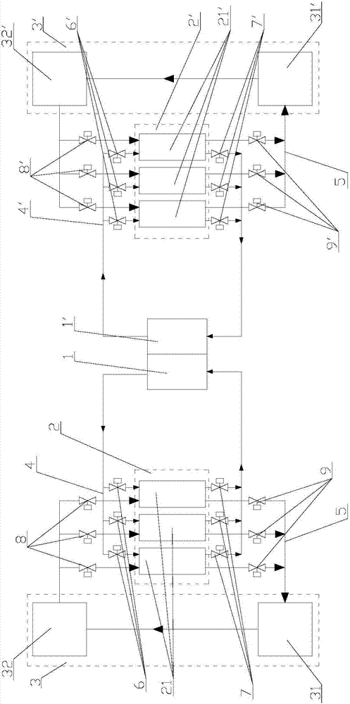
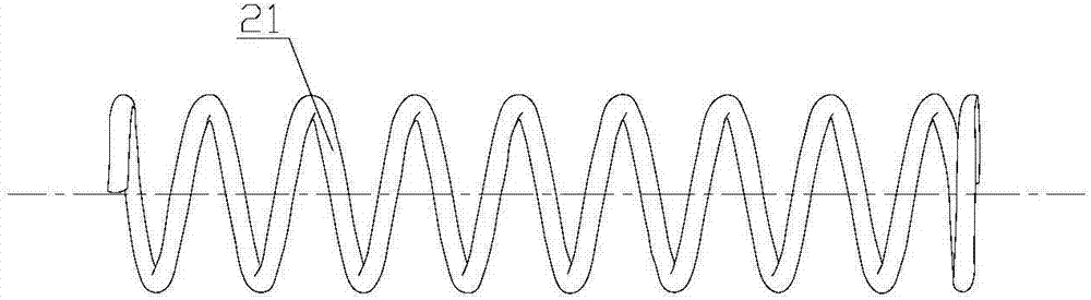
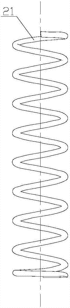
[0053] The material of the positive electrode liquid storage pipe 21 and the negative electrode liquid storage pipeline 21' is an insulating and corrosion-resistant material: polyvinyl chloride, polyethylene, polypropylene, polystyrene, polytetrafluoroethylene, polyethylene terephthalate, Nylon, polyimide, polyethernitrile, polyvinylidene fluoride, modified polyolefin, fluorosilicone rubber, dimethyl silicone rubber, methyl vinyl silicone rubber, nitrile silicone rubber, phenylene and phenylene ether silicone rubber One or a combination of several.

Embodiment 2

[0055] The positive electrode liquid storage pipe 21 and the negative electrode liquid storage pipeline 21' are stainless steel pipes.

Embodiment 3

[0057] The main body material of the positive electrode liquid storage pipe 21 and the negative electrode liquid storage pipeline 21' is stainless steel, the inner lining is stainless steel, and the outer surface is the above-mentioned insulating and corrosion-resistant material.


PUM

PropertyMeasurementUnit
lengthaaaaaaaaaa
diameteraaaaaaaaaa
lengthaaaaaaaaaa

Abstract

The invention relates to the field of energy storage batteries, and in particular to a semi-solid lithium liquid battery system and a working method thereof. The semi-solid lithium liquid battery system comprises a semi-solid lithium liquid battery, an anode liquid storage device, a cathode liquid storage device, an anode pressure driving system and a cathode pressure driving system, wherein the anode liquid storage device is communicated with an anode reaction cavity of the semi-solid lithium liquid battery through an anode liquid conveying pipeline; the cathode liquid storage device is communicated with a cathode reaction cavity of the semi-solid lithium liquid battery through a cathode liquid conveying pipeline; the anode pressure driving system is communicated with the anode liquid straoge device through an anode gas conveying pipeline; the cathode pressure driving system is communicated with the cathode liquid storage device through a cathode gas conveying pipeline; the anode liquid storage device consists of at least two anode liquid storage tubes; and the cathode liquid storage device consists of at least two cathode liquid storage tubes. Due to adoption of a plurality of liquid storage tubes, the sedimentation area of solid-phase granules of an electrode suspension is reduced, and battery leakage current is avoided.

Description

technical field [0001] The invention relates to the field of chemical energy storage batteries, in particular to a semi-solid lithium flow battery system and a working method for reducing the sedimentation of electrode suspensions and avoiding leakage current. Background technique [0002] Semi-solid lithium flow battery is a newly developed electrochemical battery technology. It combines the advantages of lithium battery and flow battery. It is a kind of battery with independent output power and energy storage capacity, high energy density and low cost. new secondary battery. It can not only be used as a supporting energy storage device for solar and wind power generation systems, but also as a peaking device for the power grid to improve the quality of power transmission and ensure the safety of the power grid. The use of chemical power sources for electrical storage and energy storage is not limited by geographical conditions, and it is expected to achieve large-scale en...

Claims


Application Information

Patent Timeline
Patent Type & Authority Applications(China)
IPC IPC(8): H01M8/18H01M8/04082
CPCH01M8/04201H01M8/188Y02E60/50
Inventor 陈永翀张晓虎陈翠杰张艳萍张萍
Owner 南京竞予能源有限公司
Why Eureka
Try Eureka