
Circulating fluidized bed coal gasification multi-stage cooling and dedusting process and device

A circulating fluidized bed and coal gasification technology, which is applied in the field of coal gasification, can solve the problems of high consumption, low filtration speed, and difficulty in cleaning dust, and achieve the effects of increasing calorific value, high heat exchange efficiency, and avoiding explosion accidents

Active Publication Date: 2017-12-01
中科清能燃气技术(北京)有限公司
View PDF6 Cites 11 Cited by
  • Summary
  • Abstract
  • Description
  • Claims
  • Application Information

AI Technical Summary

Problems solved by technology

Wet dust removal uses water spray to remove dust and cool down, which requires a large amount of primary water consumption, and the concentration of particulate matter and ammonia in the air washing water is high; dry dust removal does not produce air washing water, but the dust removal device is mainly a resistive filter made of ceramic materials Filter, low filtration speed, difficult to clean

Method used


Image

  • Circulating fluidized bed coal gasification multi-stage cooling and dedusting process and device
  • Circulating fluidized bed coal gasification multi-stage cooling and dedusting process and device
  • Circulating fluidized bed coal gasification multi-stage cooling and dedusting process and device

Examples


Embodiment 1

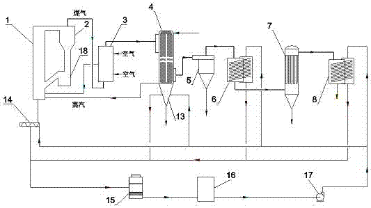
[0043] Such as figure 1 shown. The working process of this embodiment: the raw coal is added to the circulating fluidized bed gasifier 1 for reaction, the mixture of high-temperature coal gas and semi-coke generated by the gasifier 1 is separated from gas and solid by the cyclone separator 2, and the high-temperature circulating semi-coke is separated by the cyclone The feeder 18 at the bottom of the gasifier 2 directly returns to the gasifier 1 to mix and react with the raw coal to generate volatile matter and semi-coke; the volatile matter rises to the upper part of the furnace and becomes a part of the gas, and the coarser particles sink to the bottom of the furnace to be mixed with the high temperature Air and steam undergo combustion and gasification reactions; finer semi-coke particles rise to the upper part of the furnace, absorb heat from the bottom, and undergo gasification reactions with carbon dioxide and steam to generate coal gas.

[0044] The slag discharged fro...

Embodiment 2

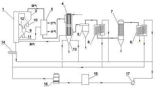
[0051] like figure 2 shown. The working process of this embodiment: the raw coal is added to the pyrolysis furnace 9, and the high-temperature circulating semi-coke obtained after gas-solid separation in the cyclone separator 2 is added to the pyrolysis furnace 9 through the return device 10 at the bottom of the cyclone separator; The high-temperature circulating semi-coke is mixed and reacted in the pyrolysis furnace 9 to produce pyrolysis gas and pyrolysis semi-coke; the pyrolysis gas is discharged from the connecting pipe 12 at the top of the pyrolysis furnace 9 and passed into the dilute phase area of ​​the gasifier 1, The pyrolysis semi-coke and solid heat carrier enter the gasification furnace 1 through the pyrolysis furnace feeder 11, and undergo combustion and gasification reactions with high-temperature air and steam; the finer semi-coke particles rise to the upper part of the furnace, absorb heat from the bottom and Gasification reaction occurs with carbon dioxide ...

Embodiment 3

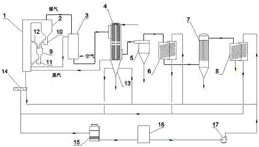
[0059] like image 3 shown. The working process of this embodiment is the same as that of Embodiment 2, the difference lies in the flow directions of gas and air in the tube-and-tube heat exchanger 3 .

[0060] In this embodiment, the high-temperature coal gas exiting the gasifier 1 is separated by the cyclone separator 2 and enters the tube side from the top of the tube heat exchanger 3, and the gas is discharged from the tube side from the bottom of the tube heat exchanger 3 after heat exchange; The lower part of the tube-and-tube heat exchanger 3 enters the shell side for heat exchange, passes through multiple baffles and turns back, and after heating up, the upper part of the tube-and-tube heat exchanger 3 exits the shell side and enters the bottom of the gasifier 1 for gasification.

[0061] The gasification furnace 1 adopts a hood to distribute air, and the working temperature at the bottom of the furnace is 1000°C, and the working temperature at the top is 945°C; the t...


PUM


Abstract

The invention provides a circulating fluidized bed coal gasification multi-stage cooling and dedusting process and device. In the process, a mixture of semicoke and high-temperature coal gas generated by a circulating fluidized bed gasifier is subjected to gas-solid separation through a cyclone separator, then the semicoke is returned to the gasifier through a return device at the bottom of the cyclone separator to continue participation in reaction while the high-temperature coal gas enters a tube side of a shell-and-tube heat exchanger, and low-temperature air enters a shell side of the shell-and-tube heat exchanger and absorbs heat energy transferred by the coal gas in heat exchange tubes; heated high-temperature air enters the bottom of the gasifier to be used for gasification; cooled low-temperature coal gas is subjected to multi-stage cooling and dedusting through a waste heat boiler, cyclone dust removal, heat pipe heat exchange, bag dust removal and heat pipe cooling prior to being used in subsequent procedures. In the process, the high-temperature coal gas discharged from the gasifier is subjected to cyclone separation and then exchanges heat with air without flowing through the waste heat boiler, the temperature of air serving as a gasifying agent is raised while a heat value of the coal gas is increased, high safety in technical operation is achieved, and great cooling and dedusting effects can be achieved by combination with multi-stage subsequent heat exchange and dedusting procedures.

Description

technical field [0001] The invention belongs to the field of coal gasification, and in particular relates to a circulating fluidized bed coal gasification multi-stage cooling and dedusting process and device. Background technique [0002] Coal gasification refers to a series of chemical reactions between the organic matter in the coal and the gasification agent (such as steam / air or oxygen) in a specific equipment at a certain temperature and pressure, and the solid coal is converted into a gas containing CO, H 2 、CH 4 Combustible gases such as CO and 2 , N 2 and other non-combustible gases. Coal gasification is the basic technology of coal energy conversion, and it is also one of the most important and key processes in the development of coal chemical industry, and it is an important way for clean utilization of coal. When coal is gasified, three conditions must be met, namely gasifier, gasifying agent, and heat. [0003] Raw coal and gasification agent undergo gasific...

Claims


Application Information

Patent Timeline
IPC IPC(8): C10J3/54C10J3/84C10J3/86C10K1/02
CPCC10J3/54C10J3/84C10J3/86C10K1/024C10K1/026C10J2300/093C10J2300/1603Y02P20/129
Inventor 不公告发明人
Owner 中科清能燃气技术(北京)有限公司
Learn More