
Wet flue gas desulfurization device and method of operating wet flue gas desulfurization device

A technology of desulfurization device and operation method, applied in separation methods, chemical instruments and methods, gas treatment, etc., can solve problems such as the inability of absorbing liquid to maintain drainage treatment standards, nozzle blockage, and solid-liquid separator blockage.

Inactive Publication Date: 2017-12-01
MITSUBISHI POWER LTD
View PDF8 Cites 1 Cited by
  • Summary
  • Abstract
  • Description
  • Claims
  • Application Information

AI Technical Summary

Problems solved by technology

Furthermore, due to the natural oxidation caused by the contact between the exhaust gas in the absorption tower and the absorbing liquid, the absorbing liquid becomes overoxidized, and there is a problem that it cannot be controlled to a desired ORP.
[0008] For example, even if the ORP is designed to be controlled at an appropriate value, the ORP is a very high value of 200 to 1000 mV, and it changes unstablely and becomes an overoxidized state. For example, the formation of manganese oxide from which manganese is oxidized, the coloring of gypsum, the generation of manganese scale, the malfunction of pH meters, the clogging of nozzles, and the clogging of solid-liquid separators, etc.
In addition, the selenium in the absorption solution is changed from the 4-valent selenium (Se 4+ ) state becomes difficult to remove hexavalent selenium (Se 6+ ) state, and persulfuric acid is generated in the absorption liquid, so there is a problem that the absorption liquid cannot maintain the wastewater treatment standard and needs to be treated in another way

Method used


Image

  • Wet flue gas desulfurization device and method of operating wet flue gas desulfurization device
  • Wet flue gas desulfurization device and method of operating wet flue gas desulfurization device
  • Wet flue gas desulfurization device and method of operating wet flue gas desulfurization device

Examples


Embodiment 1

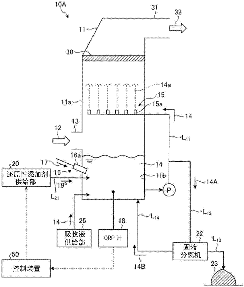
[0051] The wet flue gas desulfurization device according to the first embodiment of the present invention will be described with reference to the accompanying drawings. figure 1 It is a schematic diagram showing the wet flue gas desulfurization apparatus according to Example 1. like figure 1 As shown, a wet flue gas desulfurization device (hereinafter referred to as a "desulfurization device") 10A according to the present embodiment is provided with a gas (hereinafter referred to as "exhaust gas") 12 that removes a gas discharged from a boiler (not shown) with an absorbing liquid 14 The absorption tower 11 of sulfur oxides in the absorption tower 11; the gas introduction part 13 which is installed on the side wall 11a of the absorption tower 11 and introduces the exhaust gas 12; The absorption liquid storage part 11b of the absorption liquid 14; the circulation line L that circulates the absorption liquid 14 from the absorption liquid storage part 11b 11 ; set in the vicinit...

Embodiment 2

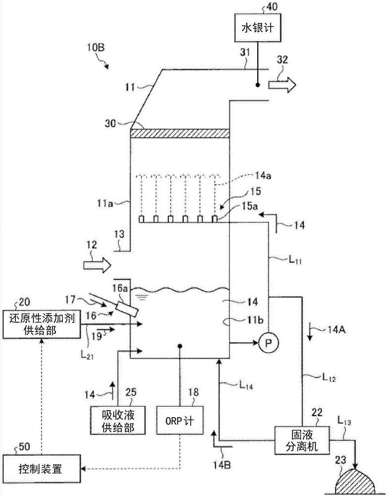
[0125] The wet flue gas desulfurization device according to the second embodiment of the present invention will be described with reference to the accompanying drawings. image 3 It is a schematic diagram showing the wet flue gas desulfurization device according to this embodiment. In addition, the same code|symbol is attached|subjected to the same member as Example 1, and the description is abbreviate|omitted.

[0126] like image 3 As shown, in the desulfurization apparatus 10B according to the present embodiment, in the desulfurization apparatus 10A of the first embodiment, the mercury meter 40 is provided in the vicinity of the exhaust duct 31 from which the purified gas 32 is discharged. In addition, when the reducing additive 19 of sulfur oxo acid system such as sodium thiosulfate is supplied as in Example 1, and the ORP based on the ORP meter 18 is adjusted to an appropriate range, the mercury meter 40 measures from the absorption tower 11 Mercury concentration in the...

Embodiment 3

[0131] The wet flue gas desulfurization device according to Example 3 of the present invention will be described with reference to the accompanying drawings. Figure 4 It is a schematic diagram showing the wet flue gas desulfurization device according to this embodiment. In addition, the same code|symbol is attached|subjected to the same member as Example 1, and the description is abbreviate|omitted.

[0132] like Figure 4 As shown, the desulfurization apparatus 10C according to the present embodiment includes the desulfurization apparatus 10A of the first embodiment, and further includes an oxidative additive supply unit 52 that supplies an oxidative additive 51 in the absorption liquid 14 or the absorption liquid storage section 11b, and supplies sulfur. As a result of the oxoacid-based reducing additive 19 , when the ORP measured by the ORP meter 18 is less than 50 mV, the oxidative additive 51 is supplied from the oxidative additive supply unit 52 . This operation contr...


PUM


Abstract

The invention relates to a wet flue gas desulfurization device and a method of operating the wet flue gas desulfurization device. The present invention comprises: an absorption tower 11 that removes sulfur oxides in an exhaust gas with an absorbent solution 14; an absorbent solution storage unit 11b that stores the absorbent solution that has absorbed the sulfur oxides; a redox potential meter 18 that measures the redox potential of the absorbent solution 14; a reducing-additive supply unit 20 that supplies a sulfur oxoacid-based reducing-additive 19 into the absorbent solution 14 or the absorbent solution storage unit 11b; and a control device 50 that controls the reducing-additive supply unit 20 on the basis of the redox potential measurement value for the absorbent solution 14 measured by the redox potential meter 18. If the redox potential measurement value exceeds an upper limit of a suitable range for the redox potential, the control device 50 controls the reducing additive supply unit 20 so as to supply the sulfur oxoacid-based reducing-additive 19.

Description

technical field [0001] The invention relates to a wet-type flue gas desulfurization device and an operation method of the wet-type flue gas desulfurization device. Background technique [0002] For example, as a desulfurization device for removing sulfur oxides in exhaust gas generated by burning heavy oil, coal, etc. in a thermal power plant, etc., the exhaust gas is mixed with a slurry-like absorption liquid (a substance composed of calcium compounds such as limestone) in an absorption tower. ) contact, absorb sulfur oxides in exhaust gas into a slurry-like absorbing liquid, oxidize the slurry-like absorbing liquid after contact, and separate solid-liquid to produce gypsum by-product. [0003] Among the sulfur oxides in the exhaust gas in this case, sulfur dioxide (SO 2 ) is absorbed by the absorption liquid through the reaction, reacts with the oxygen in the exhaust gas and the oxygen supplied from the outside, and generates gypsum. [0004] However, the oxygen concentr...

Claims


Application Information

Patent Timeline
Patent Type & Authority Applications(China)
IPC IPC(8): B01D53/50B01D53/14B01D53/78B01D53/79B01D53/80
CPCB01D53/346B01D2258/0283B01D2251/404B01D2251/606B01D53/505B01D53/508B01D53/80
Inventor 本城新太郎稻叶纪和冈本卓也桥本淳神山直行
Owner MITSUBISHI POWER LTD
Learn More