Multi-actuator system for electrohydraulic compound control of backpressure and power oil

An electro-hydraulic composite and multi-actuator technology, which is applied to fluid pressure actuation system components, fluid pressure actuation devices, servo motors, etc., can solve the problem of increasing power source emissions and energy consumption, increasing costs, and affecting popularization and application and other problems to achieve the effect of solving heat generation and aging, eliminating throttling loss and reducing installed power

Active Publication Date: 2017-12-08
TAIYUAN UNIV OF TECH
View PDF7 Cites 1 Cited by
  • Summary
  • Abstract
  • Description
  • Claims
  • Application Information

AI Technical Summary

Problems solved by technology

In the published invention patent "Energy-saving shield segment assembly and positioning electro-hydraulic control system using load-sensing technology, CN103032396A", the multi-actuator system often has the characteristics of a wide range of load changes. By adopting the load-sensing control principle, the The output pressure of the hydraulic pump always changes with the change of the load, avoiding the energy waste caused by the original system always supplying oil at the highest working pressure, and reducing the throttling loss and overflow loss, but because the output pressure of the pump can only match the highest For multi-actuator systems, the throttling loss of low-load actuator control valves caused by large load differences can never be eliminated, and this part of the loss is precisely the most important source of energy consumption for multi-actuator systems, accounting for 35%~39% of engine output power
[0003] In addition, the load of construction machinery varies in a large range during actual operation, causing the power source to often operate in a low-efficiency working area, which increases the emission and energy consumption of the power source. Therefore, it is necessary to use torque coupling to add Other forms of power sources are used to match the original power sources, such as electric / generators in the form of hybrid electric power or hydraulic pumps / motors in the form of hydraulic hybrid power. The power of the main power source, thereby improving the energy efficiency of the main power source, and under heavy load conditions, the auxiliary power source releases the absorbed energy and assists the main power source to drive the load to do work together, but the existing hybrid mode, the auxiliary power source The energy provided will be lost through the secondary throttling of the control valve, and the function is only to match the operating point of the engine. After adding this unit, the cost of the whole machine will increase a lot, and the cost recovery period will be longer, which will affect the popularization and application

Method used


Image

  • Multi-actuator system for electrohydraulic compound control of backpressure and power oil
  • Multi-actuator system for electrohydraulic compound control of backpressure and power oil
  • Multi-actuator system for electrohydraulic compound control of backpressure and power oil

Examples


Embodiment 1

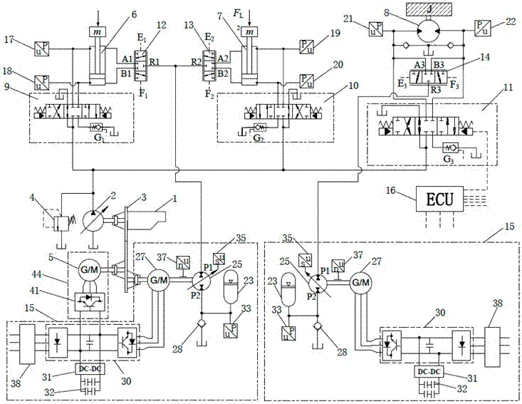
[0034] as attached figure 1 Shown is the embodiment 1 of the multi-actuator system for back pressure and power oil electro-hydraulic composite control of the present invention, which includes an electric power control unit and a back pressure control unit connected to the transfer case to control the circuit principle of three hydraulic actuators. In this system, the power source 1 is an electric motor, the main hydraulic pump 2 is a variable hydraulic pump with negative flow control, the transfer case 3 mainly transmits torque, the speed ratio of each shaft is 1:1, and the pressure of the safety valve 4 is set at 32 MPa. The first hydraulic actuator 6 is a hydraulic cylinder, the second hydraulic actuator 7 is also a hydraulic cylinder, and the third hydraulic actuator 8 is a hydraulic motor; the first control valve 9, the second control valve 10 and the third control valve 11 all use Proportional multi-way valve for negative flow control. Its constitutive relationship is to...

Embodiment 2

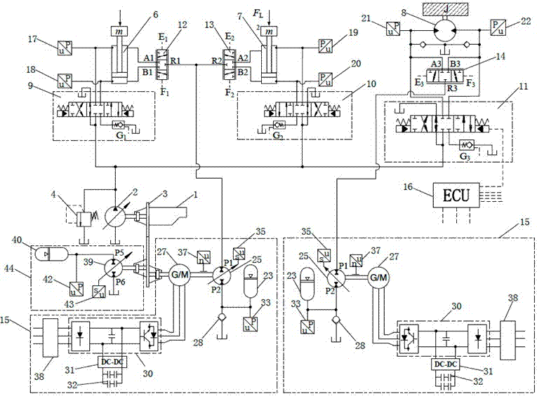
[0043] as attached figure 2 Shown is the embodiment 2 of the multi-actuator system for back pressure and power oil electro-hydraulic composite control of the present invention, which includes a hydraulic power control unit and a back pressure control unit connected to the transfer case 3 to control the circuit of three hydraulic actuators principle.

[0044] The composition and connection relationship of this embodiment 2 is similar to that of embodiment 1, the difference is that the power control unit 44 adopts a hydraulic control method, and the power control hydraulic pump / motor 25 adopts an axial plunger structure, and its drive shaft is directly connected to the branch On the moving box 3, the power regulating hydraulic pump / motor oil inlet P5 is connected with the working oil port of the power regulating hydraulic accumulator 40 and the working oil port of the eighth pressure sensor 42, and the power regulating hydraulic pump / motor oil outlet P6 is connected with the oi...

Embodiment 3

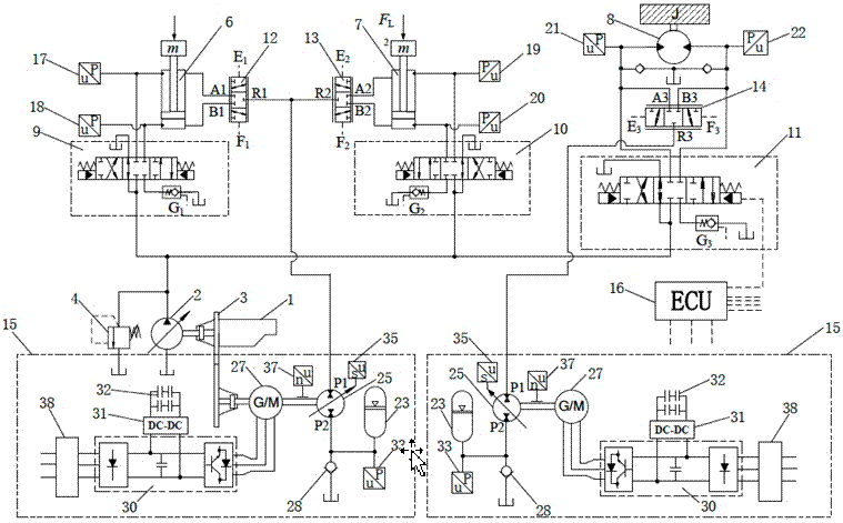
[0046] as attached image 3 Shown is the embodiment 3 of the multi-actuator system for back pressure and power oil electro-hydraulic composite control of the present invention, which uses only the back pressure control unit connected to the transfer case 3 to control the circuit principle of three hydraulic actuators. The difference between this embodiment and Embodiment 1 and Embodiment 2 is that the power regulation unit 44 is not included in the system.


PUM


Abstract

Disclosed is a multi-actuator system for electrohydraulic compound control of backpressure and power oil. A power control unit, a backpressure control unit, a controller, a switching control valve, a hydraulic control one-way valve and a pressure sensor are additionally arranged, pressure of a return oil cavity of an actuator is controlled by an electrical regeneration mode of hydraulic energy, the situation that pressure differentials of actuator control valves of the multi-actuator system under large load differential condition are identical is realized, output pressure and flow of a hydraulic pump are matched with the actuators as required, throttling loss generated from load inconformity is removed, problems that an engineering mechanical hydraulic tank is small resulting in heating and aging of hydraulic oil are solved, discharging is reduced, and energy efficiency is improved.

Description

technical field [0001] The invention relates to a multi-actuator control system in hydraulic control technology, in particular to an electro-hydraulic control technology used for power matching of engineering equipment and reducing pressure loss of a multi-actuator system. Background technique [0002] At present, various types of non-road mobile equipment such as construction machinery, road construction machinery, mining machinery, forestry machinery, and agricultural machinery generally use internal combustion engines to drive hydraulic pumps as power sources, distribute and transmit power through multi-way valves and pipelines, and control The hydraulic system with compound actions of multiple actuators is also the most widely used and most important field of hydraulic technology. It is characterized by high power density, compact structure, good maneuverability and strong environmental adaptability, but the fatal disadvantage is low energy utilization. The energy effici...

Claims


Application Information

Patent Timeline
Patent Type & Authority Applications(China)
IPC IPC(8): F15B21/08F15B1/02F15B11/16
CPCF15B1/02F15B11/16F15B21/08
Inventor 权仲翊李运帷权龙葛磊王波
Owner TAIYUAN UNIV OF TECH
Why Eureka
Try Eureka