Electric energy supply system and ceramic isolation layer

A technology of power supply and isolation layer, applied in the direction of circuits, electrical components, battery pack components, etc., can solve problems such as battery short circuit, impact on battery performance, and isolation layer disintegration, etc., to achieve proportional improvement, proper structure and distribution, and improved The effect of electrical capacity

Active Publication Date: 2017-12-08
PROLOGIUM TECH +1
View PDF8 Cites 2 Cited by
  • Summary
  • Abstract
  • Description
  • Claims
  • Application Information

AI Technical Summary

Problems solved by technology

[0009] At the same time, because ceramic particles generally have high water content, the temperature must be heated to at least 190°C to remove this adsorbed water, but the melting point of the general adhesive is not high, for example, PVDF is about 170°C, and PVDF-HEP is about 120°C. -150°C; therefore, once it is heated above 190°C to remove water, the adhesive will melt, which will change the distribution of pores inside the ceramic separator, making the charge transfer worse and affecting the performance of the battery
However, if the holes are formed by the above-mentioned plasticizers, the holes will be filled due to the melting of the adhesive, so that the ionic conductivity cannot be effectively improved.
Furthermore, if such a high temperature state is reached during operation, the adhesive will melt and the isolation layer will disintegrate, which will lead to safety problems such as short circuit, failure or explosion of the battery.
[0010] On the other hand, if polymers with high heat resistance are used entirely, such as epoxy resin (Epoxy), acrylic resin (Acrylic Acid), polyacrylonitrile (polyacrylonitrile; PAN), etc., the adhesion is good and also It can withstand high temperature, but its structure is cross-linking. The distribution of holes in the structure is not conducive to the passage of ions, which makes the ion conductivity worse, and it is difficult to apply in battery cells.
Therefore, due to the above-mentioned problems, the current ceramic isolation layer is quite difficult to be practically applied in the industry, and most of them are only placed on the electrode layer or the isolation layer in a thin film

Method used


Image

  • Electric energy supply system and ceramic isolation layer
  • Electric energy supply system and ceramic isolation layer
  • Electric energy supply system and ceramic isolation layer

Examples


Embodiment Construction

[0057] In order to clearly disclose the power supply system and its power supply unit disclosed in the present invention, several embodiments will be presented below to describe the technical features of the present invention in detail, and diagrams are also provided to demonstrate these technical features.

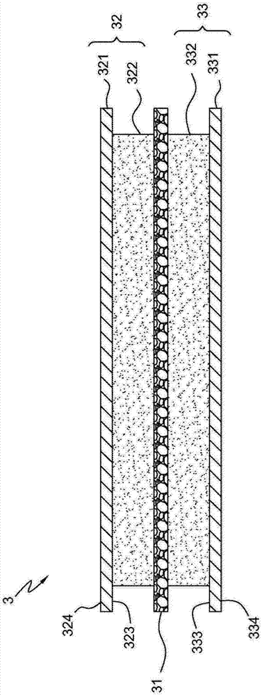
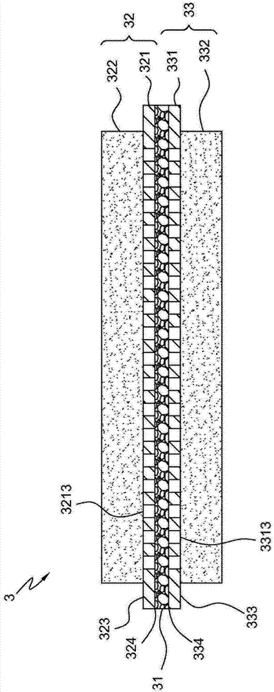
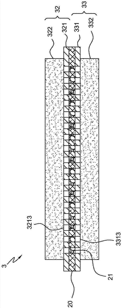
[0058] Please refer to FIG. 1A and FIG. 1B , which are schematic cross-sectional structural views of the power supply unit in a preferred embodiment of the present invention. The power supply unit 3 includes a ceramic isolation layer 31, a first electrode substrate 32, and a second electrode substrate 33, the first electrode substrate 32 includes a first collector layer 321 and a first active material layer 322, and the first collector layer 321 has The first side 323 and the second side 324 are opposite to each other, and the first active material layer 322 is disposed on the first side 323 of the first collector layer 321 . The second electrode substrate 33 includes a s...


PUM


Abstract

The invention discloses an electric energy supply system. The electric energy supply system comprises a first electrode substrate and a ceramic isolation layer, wherein the first electrode substrate comprises a first current collection layer and a first active material layer, the first current collection layer is provided with a first side surface and a second side surface which are opposite to each other, the first active material layer is arranged on the first side surface of the first current collection layer, a second current collection layer is provide with a first side surface and a second side surface which are opposite to each other, the second active material layer is arranged on the first side surface of the second current collection layer, the ceramic isolation layer is arranged between the first current collection substrate and the second current collection substrate and is formed through pasting a plurality of ceramic particles by a dual-adhesive system, and the dual-adhesive system comprises a linear macromolecule and a bridging macromolecule. The invention also discloses the ceramic isolation layer, the ceramic isolation layer is formed through pasting the plurality of ceramic particles by the dual-adhesive system, the dual-adhesive system comprises the linear macromolecule and the bridging macromolecule, and the weight percent of the bridge macromolecule accounts for 0.01-60% of the dual-adhesive system. The electric energy supply system is good in electrical conductivity and high in safety.

Description

[0001] This application is a divisional application, and the filing date of the original application is: February 7, 2012; [0002] The application number is: 201210025769.X; the name of the invention is: power supply system and its ceramic isolation layer technical field [0003] The present invention relates to a power supply unit, which is applied to power supply of various electronic devices, in particular to a power supply unit with a ceramic isolation layer that can withstand high temperature, maintains electronic insulation and increases ion conductivity. Background technique [0004] The separator (membrane) plays a key role in lithium batteries. It is between the positive and negative layers to prevent physical contact between the electrodes, and it allows free ions to pass through, while electrons are isolated to prevent A short circuit occurs. It must be chemically and electrochemically stable to the electrolyte or electrode material; and must have a certain mech...

Claims


Application Information

Patent Timeline
Patent Type & Authority Applications(China)
IPC IPC(8): H01M2/16
CPCH01M50/431H01M50/461Y02E60/10
Inventor 杨思枬
Owner PROLOGIUM TECH
Why Eureka
Try Eureka