Ring Fiber with Asymmetric Grating and Its Application in Orbital Angular Momentum Generation

An orbital angular momentum, asymmetric technology, applied in the field of optics, can solve the problems of poor long-term stability, large structure size, narrow orbital angular momentum wavelength, etc., to achieve effective separation and stable transmission

Active Publication Date: 2019-10-25
NORTHEASTERN UNIV LIAONING
View PDF4 Cites 2 Cited by
  • Summary
  • Abstract
  • Description
  • Claims
  • Application Information

AI Technical Summary

Problems solved by technology

Microbent fiber gratings have poor long-term stability due to the recovery effect of mechanical microbending, while lasers require a long rare earth-doped fiber, wavelength division multiplexer and fiber polarization controller, etc., making their structure size large and the system complex
In addition, most optical fiber structures that generate optical orbital angular momentum, such as long-period fiber gratings and fiber lasers based on double Bragg gratings, can only generate orbital angular momentum modes under a single wave, making the wavelength of orbital angular momentum generation narrow and impossible. tuning

Method used


Image

  • Ring Fiber with Asymmetric Grating and Its Application in Orbital Angular Momentum Generation
  • Ring Fiber with Asymmetric Grating and Its Application in Orbital Angular Momentum Generation
  • Ring Fiber with Asymmetric Grating and Its Application in Orbital Angular Momentum Generation

Examples


Embodiment 1

[0036] A hollow-core annular fiber with an asymmetric long-period fiber grating is used to realize the conversion between angularly non-same-order modes in the ring, including the following steps:

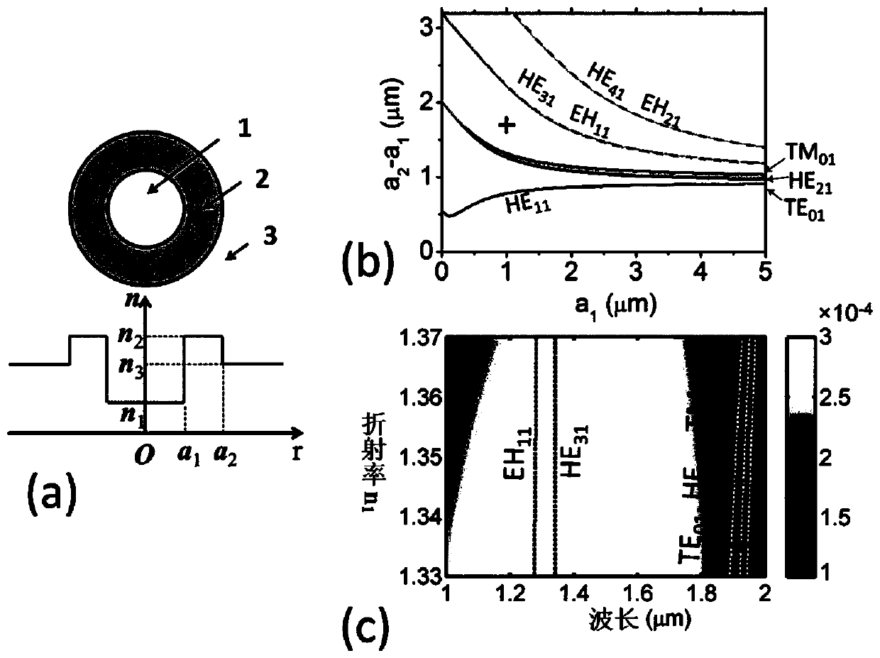
[0037] Step 1: Fabricate a hollow-core ring-shaped optical fiber by chemical vapor deposition and optical fiber drawing equipment. Hollow-core ring fibers have a high-refractive-index ring to transmit light within the high-refractive-index ring. The end face of the hollow core ring fiber is as figure 1 As shown in (a), the refractive index n of liquid filled in the hollow core 1 =1.33-1.37, high refractive index ring refractive index n 2 =1.47, cladding refractive index n 3 = 1.44. The beam modes supported in the ring core can be adjusted by adjusting the inner diameter of the ring core a 1 and outer diameter a 2 decide, such as figure 1 (b) shown. The ring core fiber size is determined as a 1 = 1 μm and a 2 =2.7μm, this parameter makes the high-refractive index ring only...

Embodiment 2

[0041] A hollow-core annular optical fiber with an asymmetric long-period grating, used for wavelength tunable orbital angular momentum mode generation, comprising the following steps:

[0042] Step 1: Fabricate a hollow-core ring-shaped optical fiber by chemical vapor deposition and optical fiber drawing equipment. Hollow-core ring fibers have a high-refractive-index ring to transmit light within the high-refractive-index ring. The end face of the hollow core ring fiber is as figure 1 As shown in (a), the refractive index n of liquid filled in the hollow core 1 =1.33-1.37, high refractive index ring refractive index n 2 =1.47, cladding refractive index n 3 = 1.44. The beam modes supported in the ring core can be adjusted by adjusting the inner diameter of the ring core a 1 and outer diameter a 2 decide, such as figure 1 (b) shown. The ring core fiber size is determined as a 1 = 1 μm and a 2 =2.7μm, this parameter makes the high-refractive index ring only support the...

Embodiment 3

[0049] A hollow-core annular optical fiber with an asymmetric long-period grating, used for wavelength tunable orbital angular momentum mode generation, comprising the following steps:

[0050] Step 1: with embodiment 2;

[0051] Step 2: Through unilateral UV exposure of the hollow core ring fiber filled with opaque liquid, the periodic refractive index modulation of the upper half ring is realized, and a hollow core ring fiber with an asymmetric grating is made. Its structure is as follows figure 2 shown. The upper half of the high-index ring is subjected to a periodic index modulation with a refractive index n 2 +Δn, the refractive index change value is Δn=2.6×10 -4 ; The refractive index of the lower half ring remains unchanged as n 2 , the grating period is 287 μm, and the number of grating periods is 40.

[0052] Step 3, step 4, step 5: same as embodiment 2;

[0053] Step 6: Adjust environmental parameters such as magnetic field, electric field, temperature, etc. to...


PUM


Abstract

The invention provides an annular optical fiber with an asymmetrical optical grating and application in orbital angular momentum generation thereof. A hollow core annular optical fiber can increase the effective refractive index between degeneracy-similar modes, thereby preventing crosstalk between the modes. A long period optical grating inscribed on the upper half ring of the hollow core annular optical fiber breaks a circular symmetry structure of the optical fiber and achieves conversion between angular non-same order modes. When input light is of a circular polarization fundamental mode, a first-order orbital angular momentum mode can be generated. The hollow core of the hollow core annular optical fiber is filled with an optical functional material with the refractive index adjustable and the wave length for generating the orbital angular momentum mode can be tuned by the refractive index of the liquid, so that the structure can generate the orbital angular momentum mode in an adjustable cross band wave length range. Simulation shows that when the optical grating period is 292 [mu]m and the optical grating length is 1.460cm, the range of broad band wave lengths with the angular momentum mode conversion rate higher than 90% can reach 237nm, the greatest conversion rate is 98.91%, and the modulation rate of the refractive index of the filling liquid for the wave lengths for orbital angular momentum mode generation is 400nm / RIU.

Description

technical field [0001] The invention belongs to the field of optical technology, and relates to a ring-shaped optical fiber with an asymmetric long-period grating and its application in the generation of orbital angular momentum. Background technique [0002] Optical orbital angular momentum corresponds to the rotation of the optical phase structure, revealing another degree of freedom of light that is completely different from spin, and thus has attracted much attention. At present, applications based on optical orbital angular momentum have made remarkable progress in the fields of microscopic imaging, target detection, optical communication, radio frequency communication, etc., but there are still many problems to be solved. The generation of optical orbital angular momentum is One of the most fundamental problems. [0003] Devices that generate orbital angular momentum modes in free space include spatial beam modulators, helical phase plates, cylindrical lenses, etc. A...

Claims


Application Information

Patent Timeline
Patent Type & Authority Patents(China)
IPC IPC(8): G02B6/02G02B6/032
CPCG02B6/02095G02B6/02171G02B6/032G02B2006/0325
Inventor 赵勇夏凤胡海峰
Owner NORTHEASTERN UNIV LIAONING
Why Eureka
Try Eureka