
Two-dimensional quick deflection reflection mirror and working method thereof

A mirror and yaw technology, applied in the field of two-dimensional fast yaw mirrors, can solve the problems of limiting the measurement accuracy of the yaw angle of fast yaw mirrors, the inability to install high-precision capacitive sensors, and the limited accuracy of measurement methods, etc. Achieve the effect of improving beam control accuracy, occupying a small space, and compact mechanism

Active Publication Date: 2017-12-15
HENAN POLYTECHNIC UNIV
View PDF4 Cites 8 Cited by
  • Summary
  • Abstract
  • Description
  • Claims
  • Application Information

AI Technical Summary

Problems solved by technology

[0005] The Chinese invention patent with the patent number "201210434727.1" and the patent name "a two-dimensional fast control mirror" adopts the method of pasting strain gauges to indirectly measure and output angular displacement information, but the measurement method based on strain gauges has limited accuracy and is also Limits the yaw angle measurement accuracy of fast yaw mirrors
[0006] Although the accuracy of the capacitive sensor is high, the fast deflection mirror disclosed in the Chinese invention patent No. , using both ends of the driver to drive the mirror to generate a deflection action. Due to space constraints, this structure cannot be installed with a high-precision capacitive sensor
[0007] The mirror surface of some yaw mirrors is placed perpendicular to the driving direction of the driver. When the temperature changes in a large range, it will cause a displacement perpendicular to the direction of the mirror surface, resulting in optical path distortion.

Method used


Image

  • Two-dimensional quick deflection reflection mirror and working method thereof
  • Two-dimensional quick deflection reflection mirror and working method thereof
  • Two-dimensional quick deflection reflection mirror and working method thereof

Examples


Embodiment Construction

[0055] In order to make the object, technical solution and advantages of the present invention clearer, the present invention will be described in further detail below with reference to the accompanying drawings and examples.

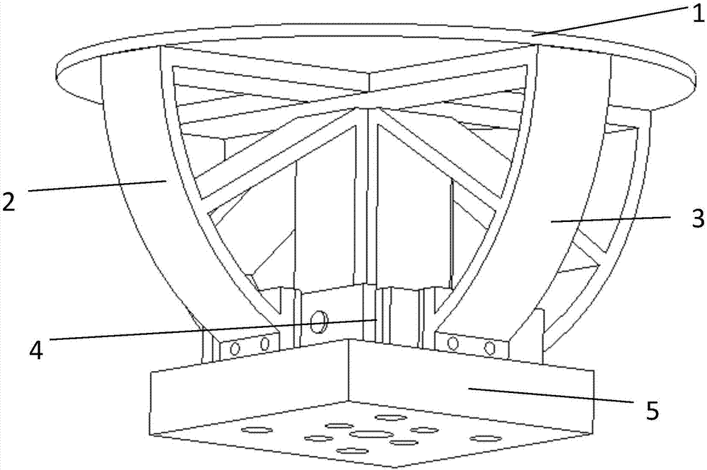
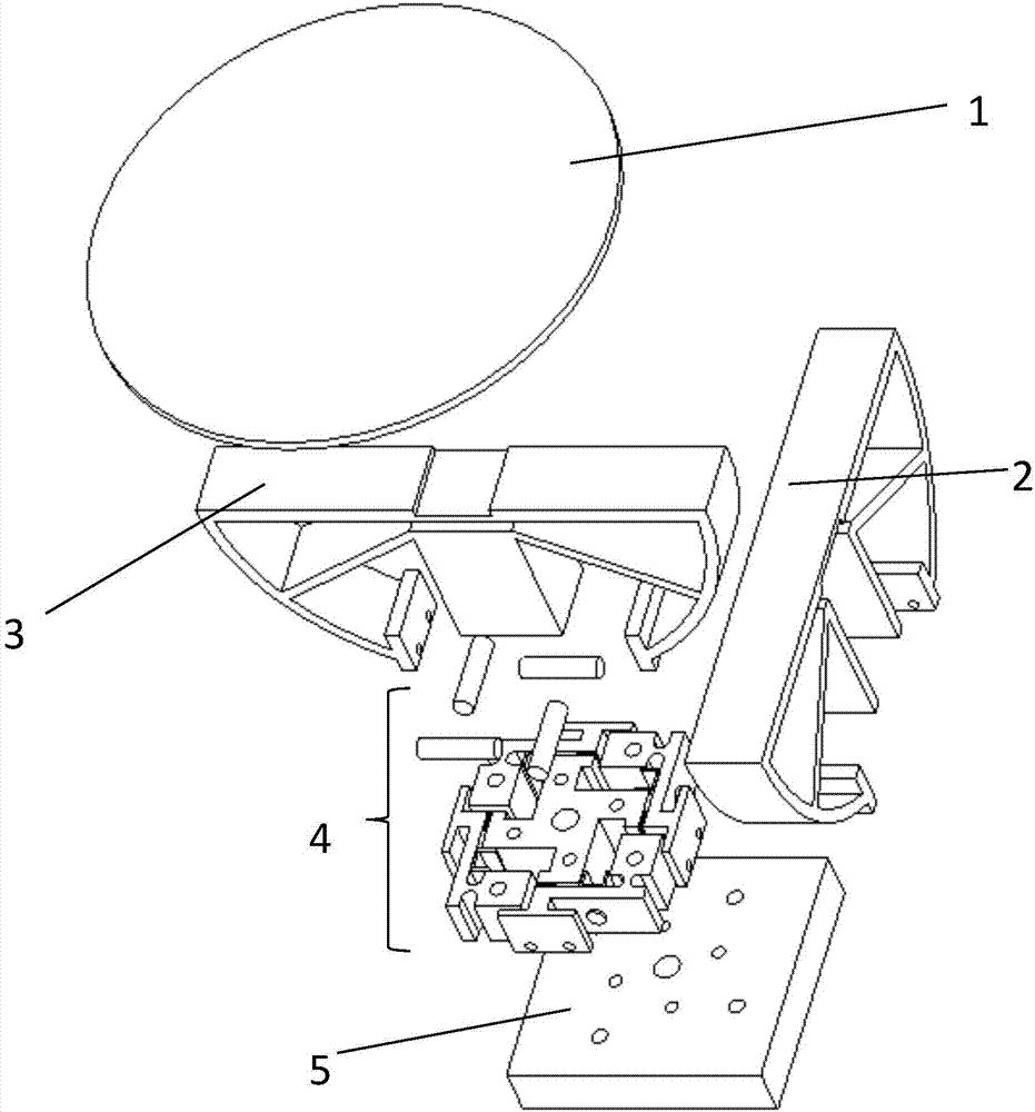
[0056] Such as figure 1 , 2 As shown, a two-dimensional fast yaw mirror includes a mirror support structure 1; a first flexible yaw mechanism 2; a second flexible yaw mechanism 3; a sensor drive assembly 4; a base 5 and a drive control system 6;

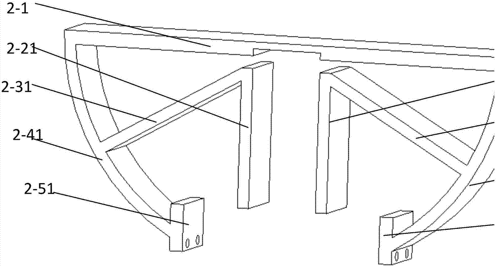
[0057] Such as image 3 As shown, the first flexible yaw mechanism 2 includes: X-direction support horizontal plate 2-1, X-direction yaw shaft first brace 2-21, X-direction yaw shaft second brace 2-22, X The first flexible leaf spring 2-31 in the direction, the second flexible leaf spring 2-32 in the X direction, the first guide plate 2-41 in the X direction, the second guide plate 2-42 in the X direction, and the first input connector 2-51 in the X direction and the second input connector 2-52 in the X dir...


PUM


Abstract

The invention discloses a two-dimensional quick deflection reflection mirror and a working method thereof. The two-dimensional quick deflection reflection mirror is characterized by comprising a mirror supporting structure, a first flexible deflection mechanism, a second flexible deflection mechanism, a sensing driving component, a base and a driving control system; the flexible deflection mechanism is used for installing the mirror supporting structure after being combined, the sensing driving component and the driving control system are connected to be used for controlling the flexible deflection mechanisms to execute deflection motions, and the base is used for fixing the sensing driving mechanism and the flexible deflection mechanisms. The two-dimensional quick deflection reflection mirror has the advantages of being easy to assemble, compact in mechanism, high in space utilization rate, good in stability, quick in response, small in size, light in weight and high in rigidity; the range of an output deflection angle is increased, so that the reflection mirror has a large deflection range; the two-dimensional quick deflection reflection mirror is high in measurement precision and small in occupied space, can indirectly measure the deflection angle, is high in deflection angle output precision, improve the beam control precision and is high in linearity and resolution.

Description

technical field [0001] The invention relates to the technical field of beam control, in particular to a two-dimensional fast-swing reflector and a working method thereof. Background technique [0002] Fast yaw mirrors are a type of key components in modern opto-mechanical systems. Their main function is to realize the angle pointing, scanning and stabilization of light by adjusting their mirror angles in real time. They have been widely used in space laser communication, autonomous Adapt to optics, compound axis precision tracking, astronomical telescope, laser imaging radar, laser beam stabilization system, confocal microscope, laser scanning and other fields. For example, in the space laser communication system, the fast deflection mirror is used to adjust and control the beam in real time, which can ensure the stability of the laser communication link. In the adaptive optics system, the fast yaw mirror adapts to changes in external conditions by continuously adjusting th...

Claims


Application Information

Patent Timeline
IPC IPC(8): G02B26/08G02B7/198
CPCG02B7/198G02B26/0858
Inventor 王耿王海涛王莹魏绍亮王帅旗周克辛
Owner HENAN POLYTECHNIC UNIV
Learn More